Thermal flowmeter

a flowmeter and flow rate technology, applied in the field of flowmeters, can solve the problems of deteriorating pressure characteristics, affecting the flow rate of the flowmeter, and the inability to confirm the sucked state of the semiconductor chip, etc., and achieves the effect of reducing the flow rate, and improving the flow ra

Inactive Publication Date: 2005-04-21
CKD
View PDF0 Cites 10 Cited by
  • Summary
  • Abstract
  • Description
  • Claims
  • Application Information

AI Technical Summary

Benefits of technology

[0018] This is because the fluid under measurement can be allowed to flow as a highly regulated flow into the sensor channel by incorporating mesh sheets in the laminate, seeing that the disturbance of flow of the fluid is diminished by passing through mesh portions. Thus, it is preferable that plural mesh sheets be incorporated in the laminate. In this case, laminating the mesh sheets through predetermined spacings is preferable to laminating them directly. This is because a greater flow uniforming effect can be obtained. Thus, it is preferable that the mesh sheets be laminated through spacers.
[0019] In the thermal flowmeter of the present invention, since the flow of the fluid under measurement flowing through the sensor channel can thus be regulated, it is possible to obtain a very stable output. Besides, the response characteristic is not impaired because an electric filter is not used.

Problems solved by technology

Recently, however, semiconductor chips have been becoming more and more small in size.
Thus, with the pressure sensor, it has become impossible to confirm a sucked state of a semiconductor chip.
However, with the thermal flowmeter which the applicant in the present case proposed in Japanese Patent Application No. 2000-368801, as shown in FIG. 32, the pressure characteristic is deteriorated as the degree of vacuum increases, and there has been a possibility that the confirmation of suction may not be done with a high accuracy.
Thus, when the flow rate in either direction cannot be detected, it is impossible to confirm release from suction although it is possible to confirm suction.
However, this flowmeter involves the problem that its output characteristic is not linear, as shown in FIG. 34.
In the case of such a non-linear output characteristic, it has so far been impossible to control clogging of a nozzle.
However, such an arithmetic circuit must be provided separately, which is disadvantageous in point of cost.
Further, the flowmeter described in Japanese Unexamined Patent Publication No. 2002-5717 involves the problem that the output becomes unstable due to the influence of a turbulent flow, as shown in FIG. 35.
That is, it has been impossible to make the confirmation of suction with a high accuracy.
Likewise, in case of using a collet type nozzle which chucks a semiconductor chip while ensuring a constant leakage quantity at all times, it has been impossible to make the confirmation of suction.
Such fluctuations in output can be eliminated by using an electric filter, but the use of an electric filter is not desirable because the response characteristic is impaired.

Method used


Image

  • Thermal flowmeter
  • Thermal flowmeter
  • Thermal flowmeter

Examples


first embodiment

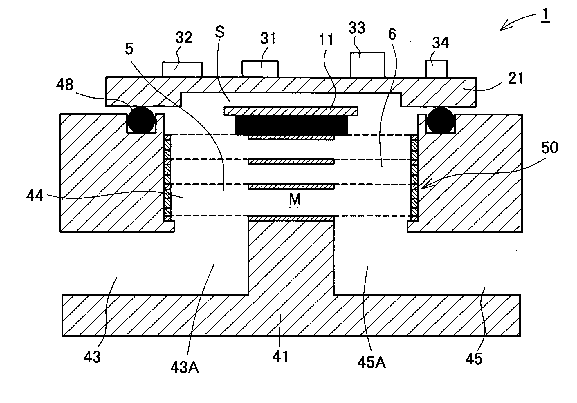
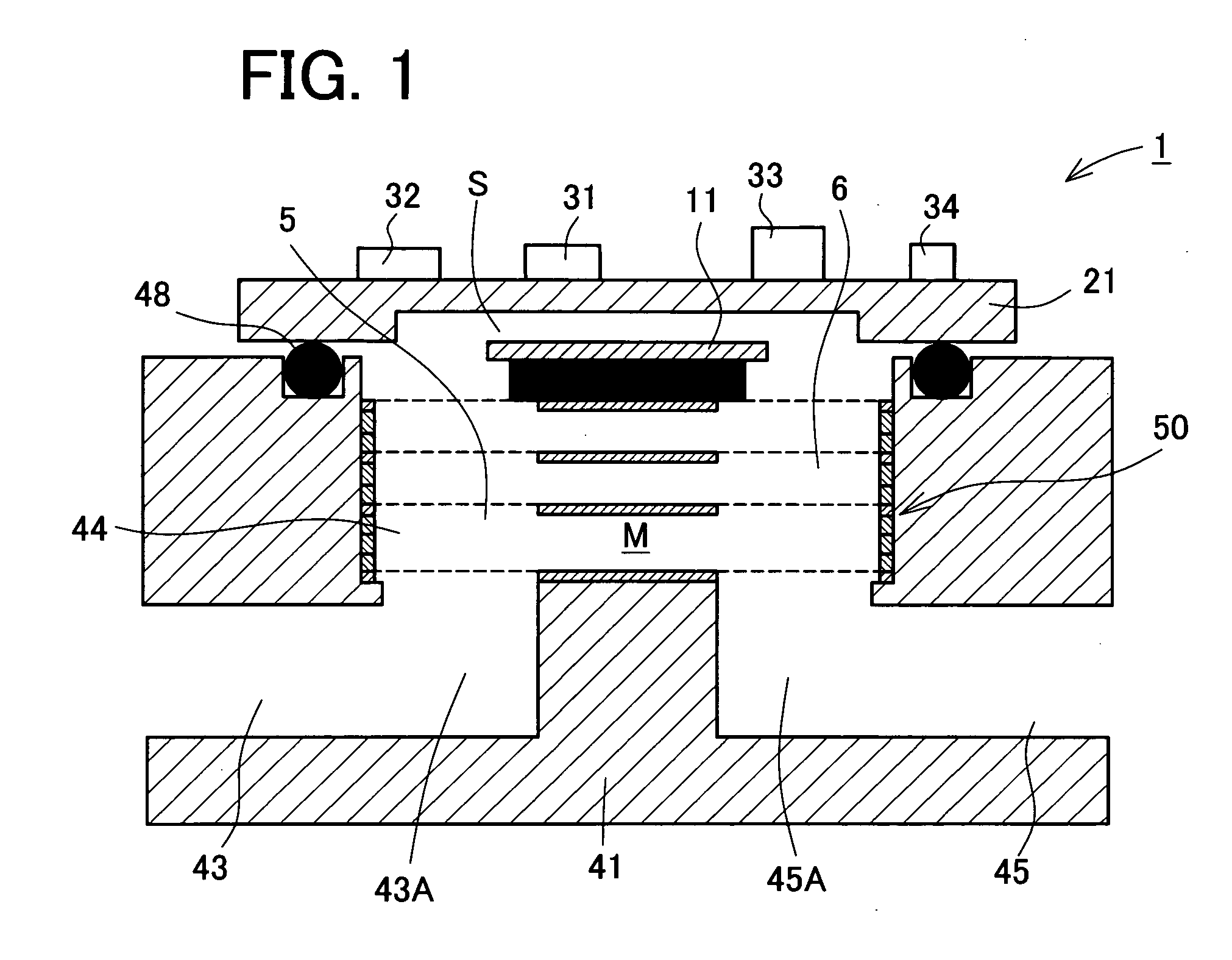
[0070] First, a description will be given of a first embodiment of the present invention. A schematic construction of a thermal flowmeter according to the first embodiment is shown in FIG. 1, which is a sectional view of the thermal flowmeter indicated at 1. As shown in FIG. 1, the thermal flowmeter 1 of this first embodiment includes a body 41, a sensor substrate 21, and a laminate 50. With the laminate 50 fitted in a channel space 44 formed in the body 41, the sensor substrate 21 is brought into close contact with the body 41 through a seal packing 48 with use of screws. In this way there are formed a sensor channel S and a main channel M as a bypass channel relative to the sensor channel S.

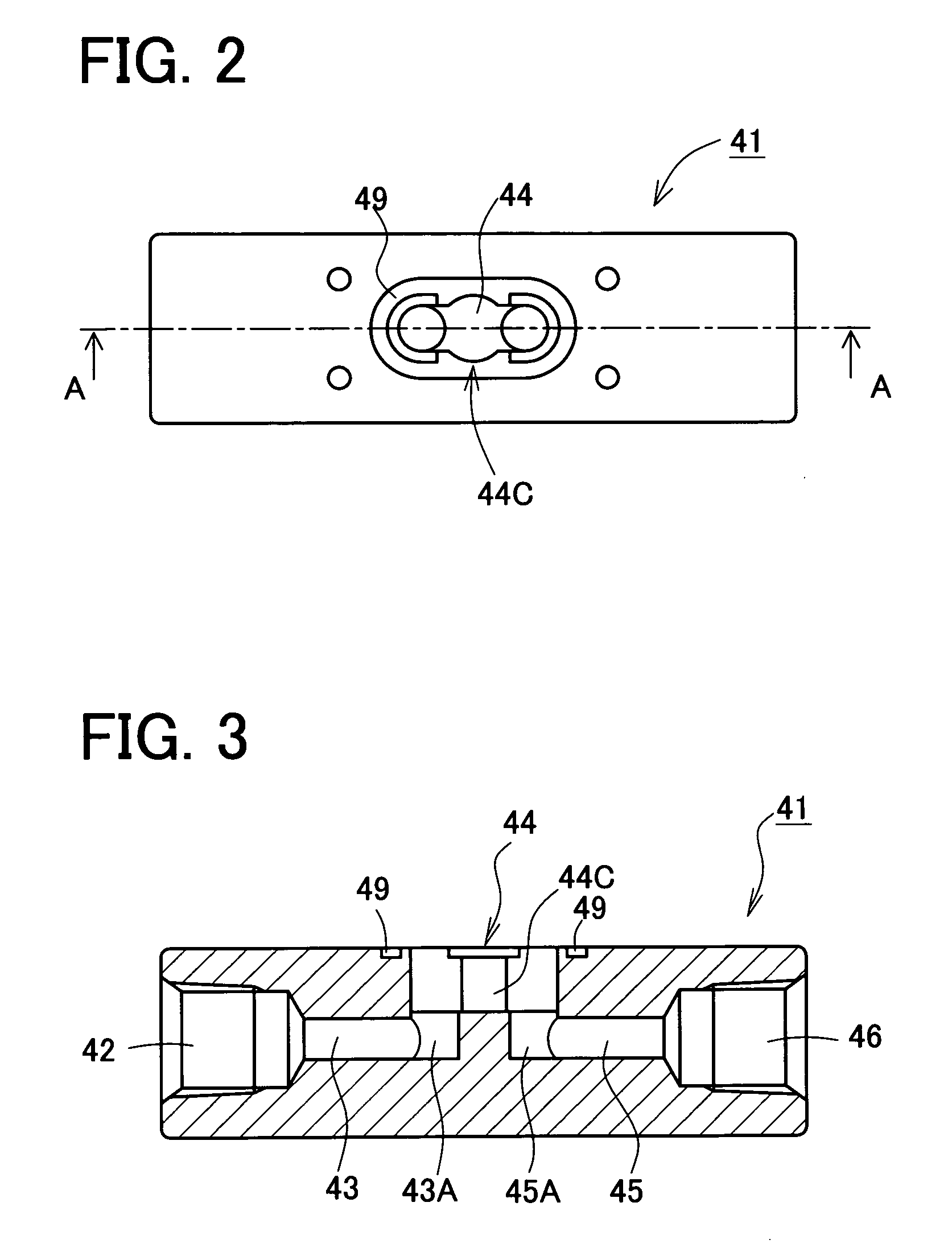
[0071] As shown in FIGS. 2 and 3, the body 41 is in the shape of a rectangular parallelepiped and is symmetric right and left. FIG. 2 is a plan view showing the body 41 and FIG. 3 is a sectional view taken on line A-A in FIG. 2. An inlet port 42 and an outlet port 46 are formed in both end fac...

second embodiment

[0108] A second embodiment of the present invention will now be described. A schematic construction of a thermal flowmeter according to this second embodiment is shown in FIG. 20. As shown in the same figure, the thermal flowmeter of this second embodiment, indicated at 101, is the same in basic construction as the thermal flowmeter 1 of the first embodiment, but is different in the shape of body in order to attain a further reduction of size. Thin sheets which constitute a laminate used in this second embodiment are also different in shape. Therefore, the different points from the first embodiment will mainly be described below. The same constructional points as in the first embodiment are identified by the same reference numerals as in the first embodiment, and explanations thereof will be omitted suitably.

[0109] First, a description will be given of a body in this second embodiment with reference to FIGS. 20 and 21. FIG. 21 is a plan view of the body. As shown in FIG. 21, the bo...


PUM


Abstract

The present invention relates to a thermal flowmeter capable of sensing a flow rate in either direction, having a linear output characteristic, and producing a stable output without impairing the response characteristic. In the thermal flowmeter, a laminate is fitted in a channel space formed in a body, forming a main channel. The laminate includes a mesh sheet so that a mesh portion is provided between the main channel and a sensor channel. A measurement chip is provided with an upstream temperature sensing resistor, a downstream temperature sensing resistor, a heating resistor, and a fluid temperature sensing resistor. By an electric circuit, the heating resistor and the fluid temperature sensing resistor are controlled to provide a constant temperature difference. Accordingly, the flow rate of a fluid under measurement is measured based on a temperature difference between the upstream and downstream temperature sensing resistors.

Description

BACKGROUND OF THE INVENTION [0001] 1. Field of the Invention [0002] The present invention relates to a thermal flowmeter for measuring a flow rate with use of resistors (hot wires). More particularly, the present invention is concerned with a thermal flowmeter which can measure the flow rate of a fluid under measurement in either direction with a high accuracy. [0003] 2. Description of Related Art [0004] Heretofore, vacuum suction has been used for handling a semiconductor chip at the time of mounting the chip, and a sucked state of the chip by vacuum suction has been confirmed using a pressure sensor. Recently, however, semiconductor chips have been becoming more and more small in size. Therefore, for example in the case of a 0.5 mm square chip, there is used a suction orifice (nozzle) having a diameter of 0.5 mm or 0.3 mm. Consequently, as shown in FIG. 30, there occurs little difference in the internal pressure of the orifice between the time when suction is performed and the tim...

Claims


Application Information

Patent Timeline
Patent Type & Authority Applications(United States)
IPC IPC(8): G01F1/68
CPCG01F1/6842G01F5/00G01F1/72G01F1/698
Inventor ITO, AKIHIROSEKO, NAOTSUGU
Owner CKD
Why Eureka
Try Eureka