Liquid level indicators

a technology of liquid level indicators and indicators, which is applied in the direction of level indicators by physical variable measurement, liquid/fluent solid measurement, engine lubrication, etc., can solve the problem of difficult to detect the level of liquid left in the container, difficult to ascertain when the container will be empty, and low temperature at which gas to liquid condensation occurs at atmospheric pressur

Inactive Publication Date: 2005-04-21
PROD INNOVATION
View PDF3 Cites 45 Cited by
  • Summary
  • Abstract
  • Description
  • Claims
  • Application Information

AI Technical Summary

Benefits of technology

[0029] Suitably, the main body contains, part at least of each of the plurality of temperature sensors, the processor, part at least of the indicator means and the one or more battery. Suitably, part at least of each of the plurality of temperature sensors extends from an exterior surface of the housing. The housing may further comprise a divider to separate the electronic components from the one or more battery, so that the battery can be changed without exposing the electronic components.
[0034] Preferably, the housing is designed to provide the temperature sensors with a degree of protection from the external environment, including heat and / or moisture. Suitably, each of the plurality of temperature sensors is spaced below the top wall of the housing, such that the upper part of the housing will provide some protection for the uppermost temperature sensor from the external environment. Suitably, each of the temperature sensors is located towards the central meridian of the front wall of the housing, such that the sides of the housing will provide a degree of protection for the temperature sensors from the external environment.
[0035] Protection of the sensors may be effected by shaping the housing such that parts of the housing provide a shield against the external environment. For example, the upper end, when arranged for use, may include a lip extending from an edge of the cover. Preferably, the lip extends from the top wall of the cover. The housing may further comprise a skirt around the region in which the temperature sensors are located extending from the surface of the housing, to provide a further shield from the external environment.
[0037] The shielding portions may be arranged such that a sealed space around the temperature sensors is effectively formed when the liquid level indicator is arranged against a surface for use.
[0039] The housing may include a hole in a wall thereof to allow sound emitted from any audio alarm to be transmitted more effectively from the device. The hole is suitably located in the region of the sound generator. The hole is suitably filled by the sound generator, such that substantially no opening between the exterior environment and the interior of the housing exists at that location. The housing may be shaped to more effectively allow for transmission of the sound from the level indicator.
[0056] The intermittent taking of readings from the temperature sensors prolongs the useful life of the batteries.

Problems solved by technology

However, the temperature at which gas to liquid condensation takes place at atmospheric pressure is often very low, for example, at atmospheric pressure propane gas condenses to a liquid at −43° C.
A problem associated with pressurized containers of volatile liquids is that it is generally difficult to detect the level of liquid left in the container.
Therefore, it is difficult to ascertain when the container will become emptied.
This is a particular problem in use of liquid propane and butane cylinders with, for example, gas powered grills, patio heaters, room heaters, refrigerators, cookers and the like.
In such instances it is unusual for a consumer to have a spare fuel cylinder available, and it can be very inconvenient if the gas bottle becomes empty part way through cooking a meal or such like.
Whilst such a device is cheap to manufacture and easy to use, it can be adversely affected by external temperature changes, such as sunlight and / or wind or rain incident on the device.

Method used


Image

  • Liquid level indicators
  • Liquid level indicators
  • Liquid level indicators

Examples


Embodiment Construction

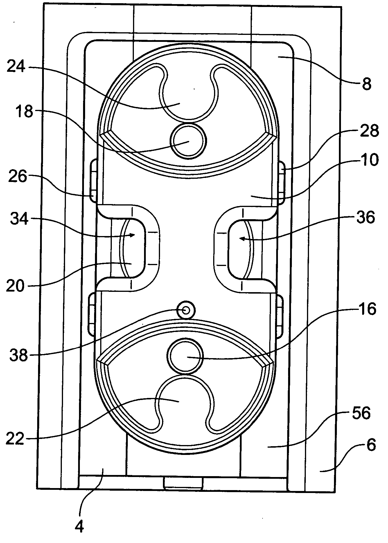
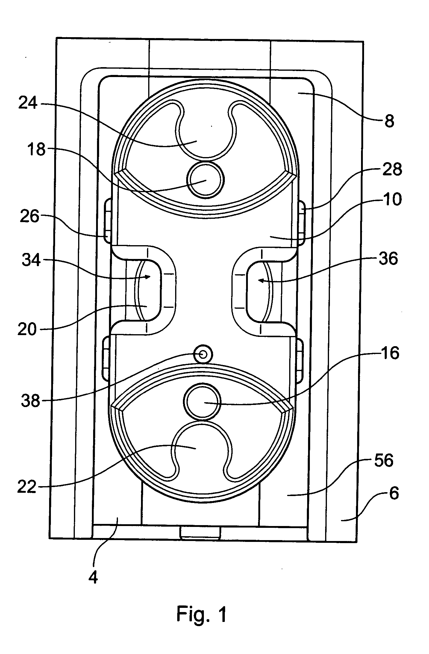
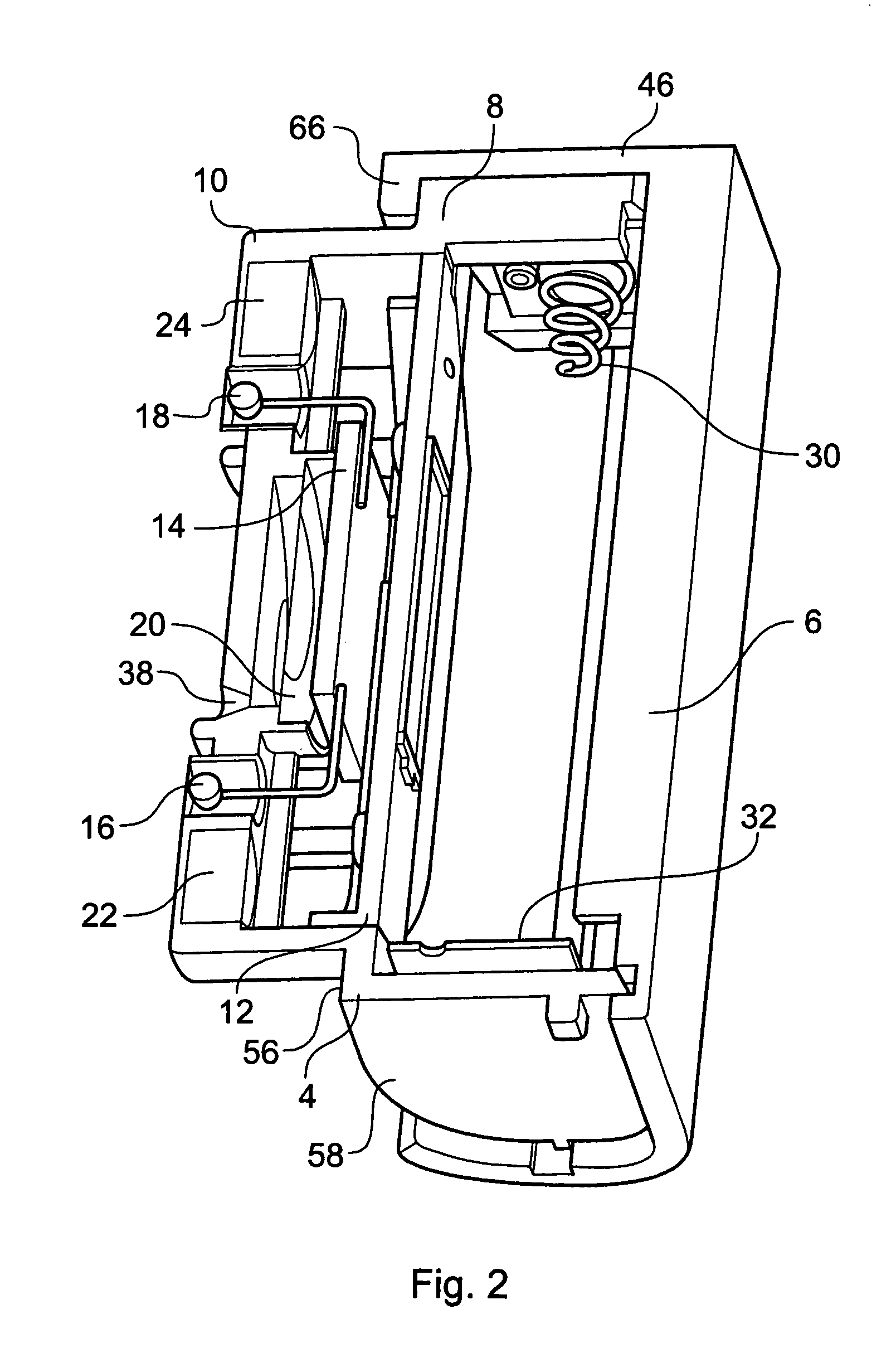
[0073] The device of FIGS. 1 to 10 comprises a housing 2 having a main body 4 (FIG. 8) and a cover 6 (FIGS. 9 and 10).

[0074] The main body 4 comprises a generally rectangular main portion 8 and a box-like, generally rectangular portion 10 extending therefrom. The main portion 8 and the box-like portion 10 are separated by means of a dividing plate 12 (FIG. 2). The box-like portion 10 contains a printed circuit board (PCB) 14, two temperature sensors (preferably thermistors) 16, 18, a piezo-electric sound generator 20, magnets 22 and 24, and LED lenses 26 and 28. The main portion 8 of the main body 4 comprises electrical contacts 30, 32 connected to the PCB 14 by wires. The main portion 8 is designed to receive two AA batteries (not shown) in a side-by-side relationship. The temperature sensors 16, 18 are separated by a distance of about 3 cm in this embodiment.

[0075] The front of the box-like portion 10 has a cut away section 34, 36 molded in each side thereof in the region of the...


PUM


Abstract

A liquid level indicator, suitable for determining the level of a volatile liquid within a container, includes temperature sensors spaced vertically apart from each other. A processor processes the outputs of the temperature sensors and produces an indication, such as an audible indication by an audible alert device, when liquid level is detected. The determination of liquid level can be by one or more of various temperature processing techniques, including difference in temperature between temperature sensors, and / or difference in temperature over time at one or more of the temperature sensors.

Description

[0001] The present invention relates to a device for and method of indicating a liquid level in a container, in particular, although not exclusively, for volatile liquids. BACKGROUND OF THE INVENTION [0002] Most gases will condense into a liquid form if the temperature of the gas is reduced sufficiently. However, the temperature at which gas to liquid condensation takes place at atmospheric pressure is often very low, for example, at atmospheric pressure propane gas condenses to a liquid at −43° C. [0003] The temperature at which condensation occurs can be increased by increasing the pressure of the gas. Some gases, such as propane and butane, for example, can be easily condensed into a liquid form by compressing the gas. Such compressed gases are often known as volatile liquids, because they will vaporize to form a gaseous state as soon as the pressure is reduced. Therefore, in order to maintain the compressed gas in the liquid form the pressure must be maintained. This is usually ...

Claims


Application Information

Patent Timeline
Patent Type & Authority Applications(United States)
IPC IPC(8): G01F23/22
CPCG01F23/22
Inventor FRANK, PETER ANDREW
Owner PROD INNOVATION
Why Eureka
Try Eureka