Driver interface system for steer-by-wire system

a technology of steering wheel and interface system, which is applied in the direction of steering linkage, electrical steering, transportation and packaging, etc., can solve the problems of not being able to alert the driver and not providing sufficient torque, and achieve the effect of preventing the rotation of the steering wheel

Inactive Publication Date: 2005-04-21
NISSAN MOTOR CO LTD
View PDF24 Cites 52 Cited by
  • Summary
  • Abstract
  • Description
  • Claims
  • Application Information

AI Technical Summary

Benefits of technology

[0007] In accordance with this invention, a steer-by-wire system is provided for an automotive vehicle that includes road wheels coupled to a rack. An electric motor is operatively coupled to the rack to laterally displace the rack and thereby alter road wheel orientation. The system further comprises a road wheel sensor for providing a signal to a controller to determine change in road wheel orientation in response to a steering command. In accordance with this invention, the system comprises a driver interface subsystem that includes a steering wheel mounted on a steering column and rotatable by a driver for inputting a steering command. The driver interface subsystem also includes a reaction torque generator and an electromechanical brake coupled to the steering column. During operation, the controller receives the signal from the sensor and determines whether the road wheel orientation corresponds to a limit, such as when the road wheels engage a mechanical stop mounted on the vehicle or are prevented from movement by a curb or other external impediment. The controller then actuates the electromechanical device to prevent rotation of the steering wheel. Thus, the driver is alerted based directly upon the responsiveness of the road wheels, in contrast to systems that apply an arbitrary end of travel limit to steering wheel rotation. Moreover, the end of travel brake for the steering wheel is accomplished independent from the operation of reaction torque generator, and thus allows the design of the reaction torque generator to be optimized to provide the desired steering feel.

Problems solved by technology

The motor is sized to generate torque to produce the desired steering feel, but does not provide sufficient torque to lock the steering column, so is not able to alert the driver when the road wheels have engaged a stop or are otherwise prevented from turning.

Method used


Image

  • Driver interface system for steer-by-wire system
  • Driver interface system for steer-by-wire system
  • Driver interface system for steer-by-wire system

Examples


Embodiment Construction

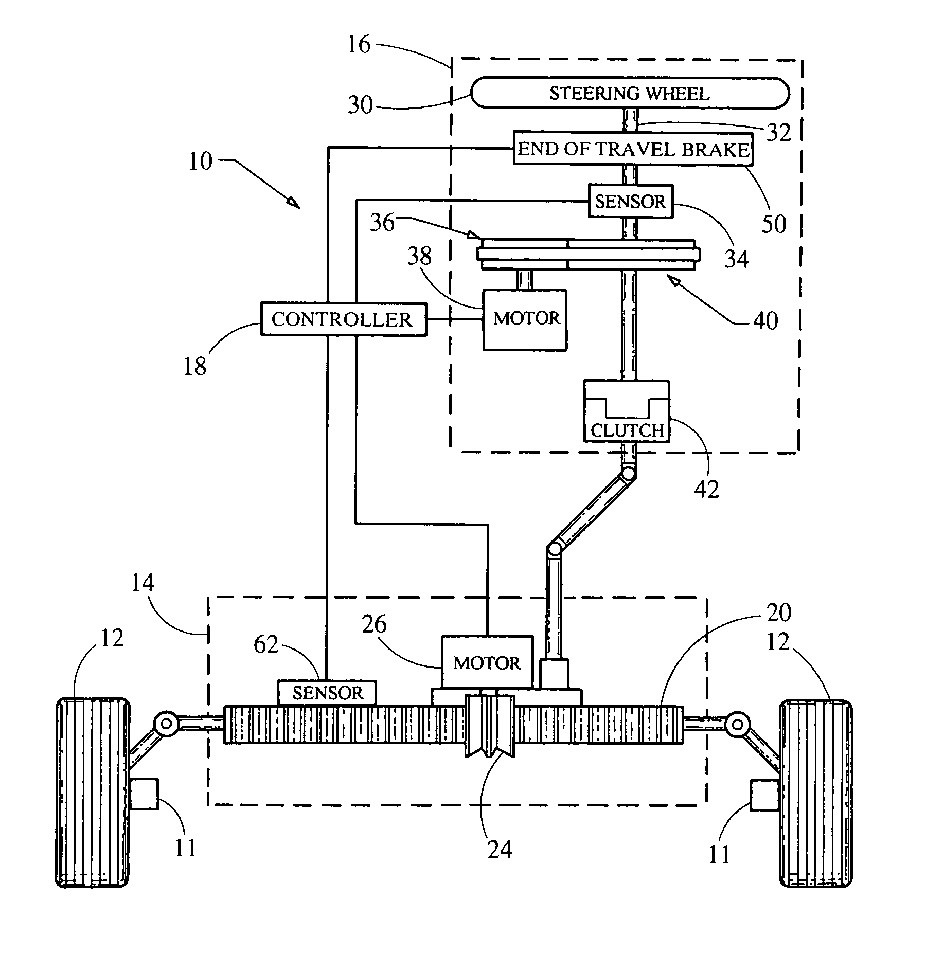
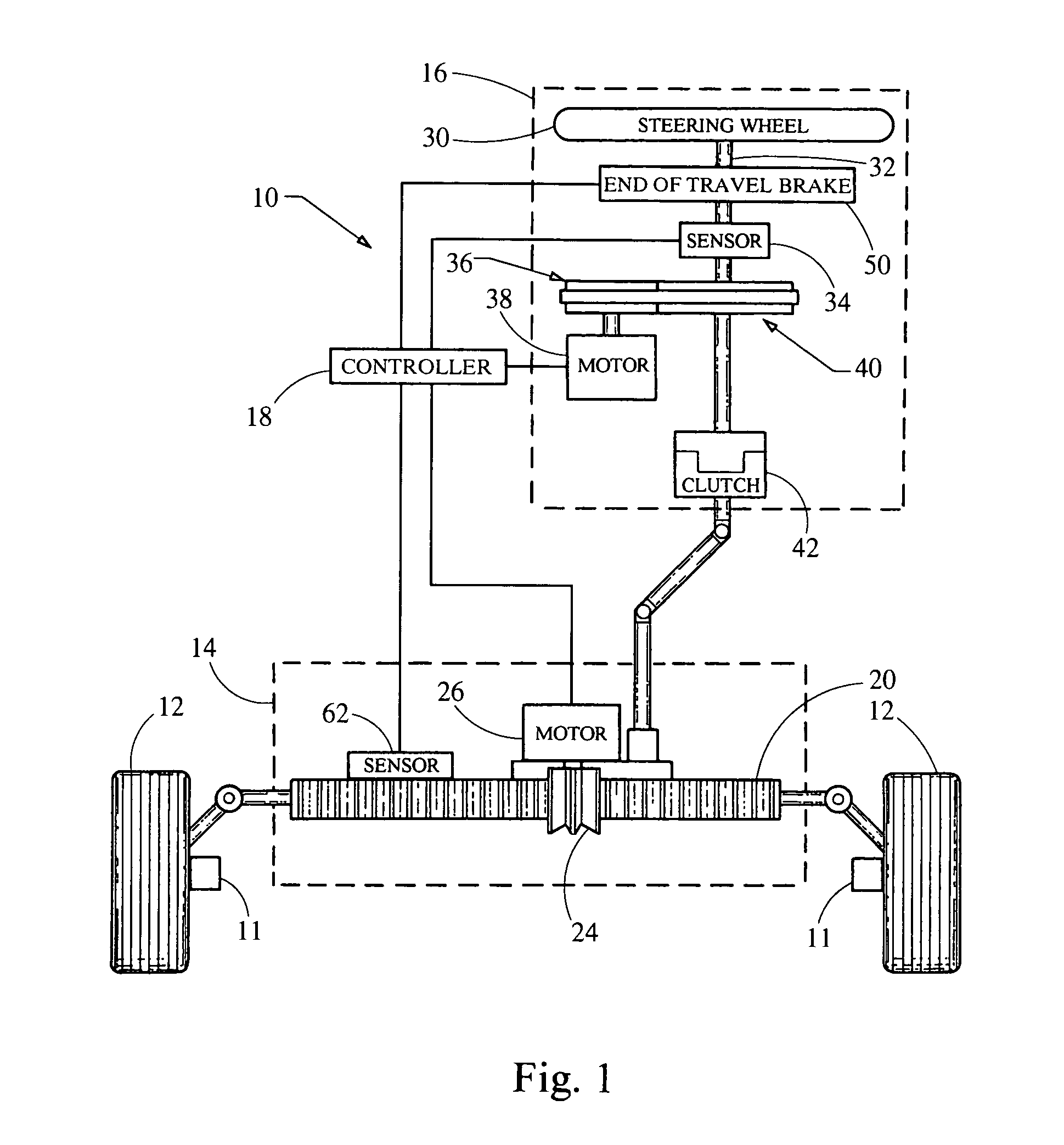
[0011] In accordance with the preferred embodiment of this invention, referring to FIG. 1, a steer-by-wire system 10 is provided for an automotive vehicle and adjusts the orientation of road wheels 12 to alter the direction of travel of the vehicle between limits that occur when road wheels 12 engage stops 11 mounted on the vehicle. Steer-by-wire system 10 comprises, as major components, a road wheel actuator subsystem 14, and a driver interface subsystem 16, linked to a computer controller 18.

[0012] Road wheel actuator subsystem 14 preferably comprises a rack 20 mechanically connected to road wheels 12 through linkages that alter the orientation of the road wheels in response to lateral displacement of the rack. Rack 20 comprises teeth that engage a pinion gear 24 that is driven by an electric motor 26. During operation, electric motor 26 is actuated in response to a signal from controller 18 and drives pinion 24, thereby laterally displacing rack 20.

[0013] Referring to FIGS. 1 a...


PUM


Abstract

A steer-by-wire system for an automotive vehicle comprises a driver interface system that includes a steering wheel mounted on a steering column. A reaction torque generator is coupled to the steering column for applying a resistive torque in response to a steering command to create a steering feel. An electromechanical brake, such as a magnetorehological brake, is also coupled to the steering column. During operation, a controller receives an input signal indicative of road wheel response to a steering command and determines when the road wheels have reached a limit, such as by engaging mechanical stops mounted on the vehicle or prevented from movement by curb or other external obstacle. In response, the controller actuates the electromechanical device to prevent rotation of the steering wheel and thereby alert the driver that the road wheels have reached a limit.

Description

TECHNICAL FIELD OF THE INVENTION [0001] This invention relates to a steer-by-wire system that includes a driver interface system comprising a steering wheel. More particularly, this relates to such system wherein the steering wheel is rotatable by an operator between limits that are dependent upon the ability of the road wheels to respond. BACKGROUND OF THE INVENTION [0002] In a conventional automotive vehicle, steering is accomplished by adjusting the orientation of the front road wheels. The road wheels pivot, either left or right, between stops that mechanically limit the orientation of the road wheels to assure operation within a safe turning radius. For example, the stops may be positioned to allow the wheels to turn within an angle of plus or minus 30° relative to a straight direction of travel. In a conventional steering system, the steering wheel is mechanically coupled to the road wheels through a rack and pinion mechanism wherein rotation of the steering wheel by the drive...

Claims


Application Information

Patent Timeline
Patent Type & Authority Applications(United States)
IPC IPC(8): B62D5/00B62D5/04B62D6/00
CPCB62D5/005B62D6/008B62D5/0469B62D5/006
Inventor HUSAIN, MUQTADAOYNOLAN, JOHN G.PLATZ, JOSEPH A.DAUGHERTY, BRIAN E.PALMER, ROBERT T.BALINT, JOHN R. III
Owner NISSAN MOTOR CO LTD
Why Eureka
Try Eureka