Laser-welded assembly

a technology of laser beam and assembly, applied in the field of assembly, can solve the problems of wasting a lot of labor in inventory control, wasting a lot of labor in manufacturing or assembling, and reducing the efficiency of assembly, and achieve the effect of convenient utilization of the single laser beam emitting devi

Inactive Publication Date: 2005-04-21
TOYOTA JIDOSHA KK
View PDF6 Cites 23 Cited by
  • Summary
  • Abstract
  • Description
  • Claims
  • Application Information

AI Technical Summary

Benefits of technology

[0025] According to the arrangement described above, in both of the welding operations of welding or bonding the first member to the base body and the second member to the first member, a direction of irradiation (incidence) of the laser beam can be made to have a component from the first and second members toward the base body. This arrangement eliminates, in both of the welding operations described above, a need of changing the posture of the pre-bonded assembly including the base body, the first member and the second member. For instance, the pre-bonded assembly need not be inverted during the welding operations. Further, it is not necessary, in the welding operations, to largely change a position of a laser beam emitting device used in the welding operations since the direction of irradiation of the laser beam to be emitted can be made to have the above-described component. Therefore, the present arrangement permits easy utilization of the single laser beam emitting device both in bonding the first member and the base body and in bonding the first member and the second member. Alternatively, the present arrangement permits the welding operation of the first member and the base body and the welding operation of the first member and the second member to be conducted at the same time by using a plurality of laser beam emitting devices.

Problems solved by technology

In the conventional arrangement, however, it is necessary to form internally threaded holes and through-holes for the bolts in the base body and the cover, respectively, taking a lot of labor in processing.
Further, the number of components is undesirably increased, taking a lot of labor in inventory control and fabricating or assembling.
Where a seal member is interposed between the cover and the base body for maintaining the fluid-tightness at the fixed portions of the base body and the cover, this results in a lot of labor in the above-described processing, inventory control and fabricating or assembling.
While the above-described explanation is made with respect to the hydraulic pressure control device for the hydraulically operated brake system for the vehicle, problems similar to those indicated above are found in other devices having a structure similar to that of the hydraulic pressure control device, such as a fluid control device of a suspension of the vehicle.
These assemblies suffer from problems similar to those described above.

Method used


Image

  • Laser-welded assembly
  • Laser-welded assembly
  • Laser-welded assembly

Examples


Embodiment Construction

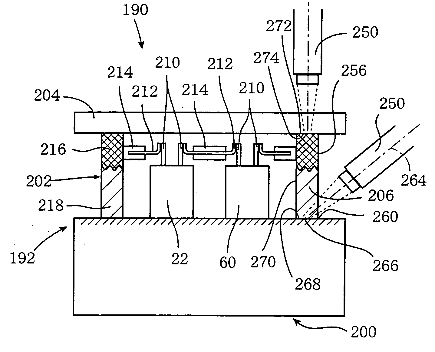
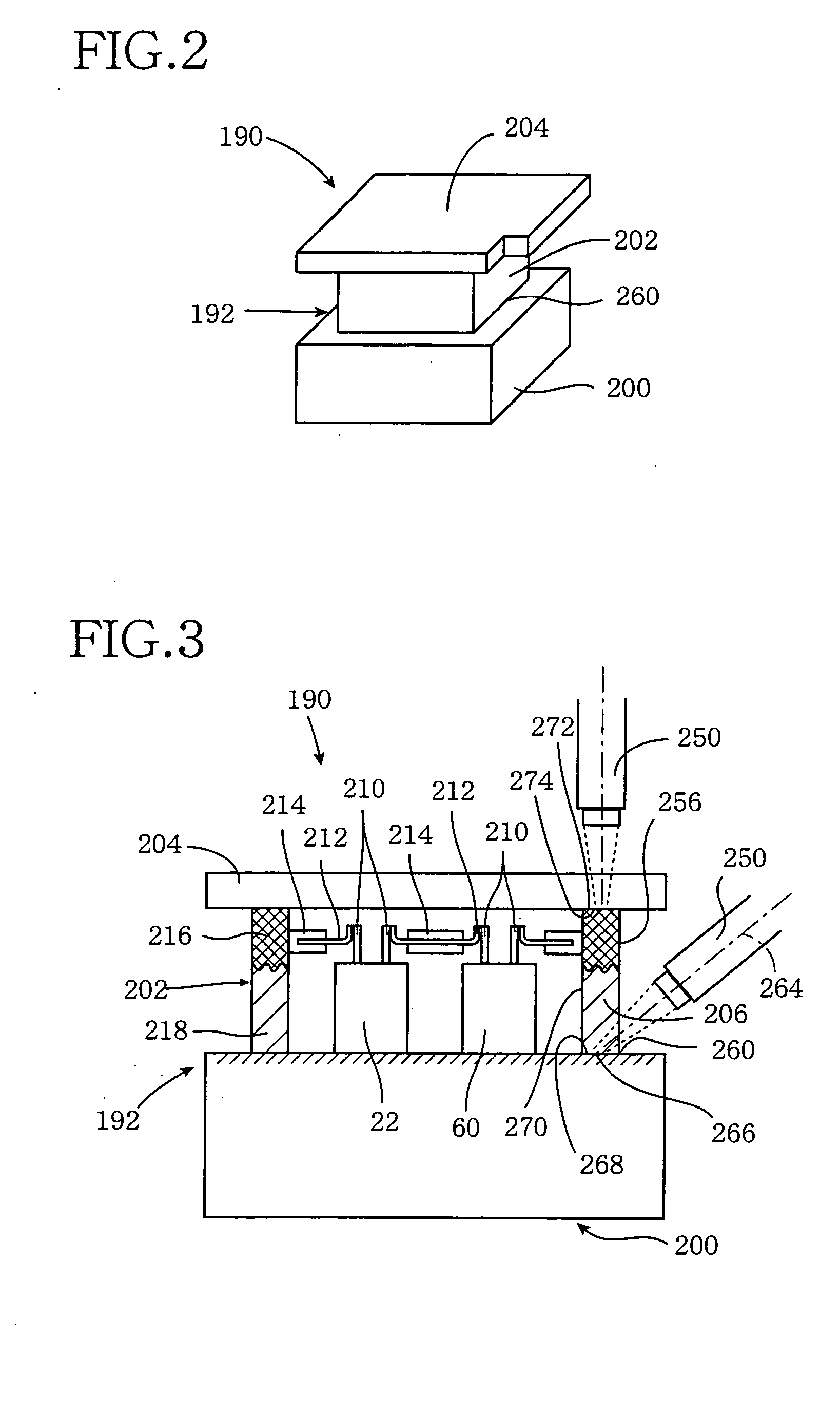
[0045] The hydraulic pressure control device according to the present invention has a body assembly in which a plurality of functional components for increasing and decreasing the hydraulic pressure, and other components are disposed. Initially, there will be described briefly an anti-lock brake system for a motor vehicle which includes the hydraulic pressure control device. Then, there will be described in detail the body assembly of the hydraulic pressure control device.

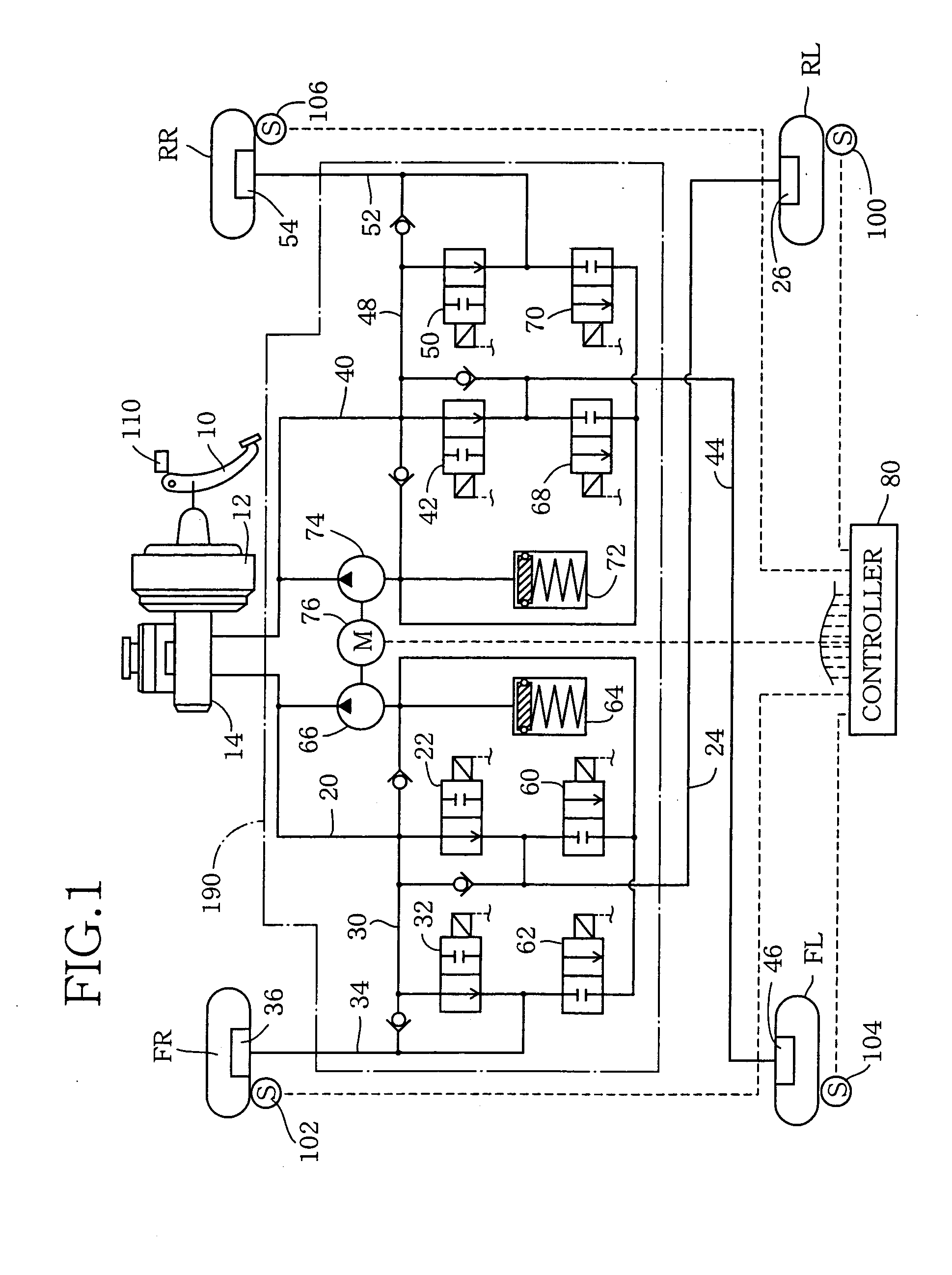
[0046] In FIG. 1, the reference numeral 10 denotes a brake pedal connected to a master cylinder 14 through a booster 12. The master cylinder 14 is of a tandem type having two pressure chambers arranged in series in which equal brake pressures are generated.

[0047] The present brake system is of an X-piping type in which mutually independent two piping systems are arranged in an “X”-like form. In the first piping system, one of the pressure chambers of the master cylinder 14 is connected to a brake cylinder 26 for ...


PUM

PropertyMeasurementUnit
angleaaaaaaaaaa
thicknessaaaaaaaaaa
thicknessaaaaaaaaaa

Abstract

A metal member and a resin member, or two resin members are welded or bonded to each other at welding or bonding surfaces thereof which are heated by irradiation of a laser beam, thereby providing an assembly wherein the two members are fluid-tightly bonded at the bonding surfaces. The laser beam is transmitted through a laser transmitting resin, and a laser absorbing material which is in contact with the laser transmitting resin is irradiated with the laser beam, so that the laser absorbing material is heated, whereby the laser transmitting resin and the laser absorbing resin are melted owing to the heat. By moving the spot of the laser beam, portions of the resin members to be heated and melted displace, and the resin materials are melted and then solidify. The casing 202 includes an upper part 216 formed of the laser absorbing resin and a lower part 218 formed of the laser transmitting resin. The casing 202 is fixed to a housing 200 formed of the laser absorbing resin, and a contact portion 268 of the upper surface of the housing 200 is irradiated with a laser beam emitted from the laser beam emitting device located outside the casing 202 such that the laser beam is emitted from the upper side of the housing 200 and is obliquely incident on the contact portion 268. The contact portion 268 is irradiated with the laser beam as described above with the location to be irradiated by the laser beam being moved at a constant speed along and throughout the periphery of the casing 202 along walls 206 thereof, whereby the casing 202 and the housing 200 are welded or bonded to each other. The lid 204 formed of the laser transmitting resin is fixed onto the casing 202, and the lid 204 and the casing 202 are welded or bonded to each other by the laser beam emitted from the emitting device located above a contact portion 272 of an upper surface of the casing 202.

Description

TECHNICAL FIELD [0001] The present invention relates to an assembly which includes a base body, a functional component(s) provided on one side of the base body, and an enclosing member fixed to a surface of the base body located on the above-indicated one side of the base body, such that the enclosing member encloses the functional component(s), or an assembly which includes a base body, a first member fixed to one surface of the base body, and a second member fixed to the first member. The invention also relates to a method of producing such assemblies. BACKGROUND ART [0002] One example of such assemblies includes a hydraulic pressure control device for a hydraulically operated brake system for a vehicle. The hydraulic pressure control device generally includes a plurality of solenoid-operated valves. The plurality of solenoid-operated valves are collectively disposed on one base body wherein there are formed fluid passages through which the solenoid-operated valves are connected t...

Claims


Application Information

Patent Timeline
Patent Type & Authority Applications(United States)
IPC IPC(8): B29C45/16B29C65/00B29C65/16F16B5/08B29C65/78B60T8/36F16B11/00
CPCB29C45/16Y10T477/649B29C65/1635B29C65/1661B29C65/1677B29C65/168B29C65/169B29C65/1693B29C65/78B29C65/7802B29C65/7814B29C66/13B29C66/3452B29C66/53462B29C66/73366B29C66/742B29C66/863B29C66/90B29K2067/00B29K2067/006B29K2077/00B29K2307/00B29K2309/08B29K2705/00B29K2705/02B29K2705/12B29K2995/0025B29K2995/0026B29K2995/0067B29K2995/0072B60T8/3675B29C65/1616Y10T477/648Y10T477/693958B29C66/919B29C66/9241B29C66/91935B29C66/91931B29C66/9161B29C66/112B29C66/114B29C65/1654B29C66/939B29C66/93431B29C66/53461B29C66/91411B29C65/00B29C66/73921B29C66/7332B29C66/73341B29C66/24221B29C66/24243B29K2995/0027B29C66/73343B29C66/71B29L2031/3481B29C66/7392B29C66/61B29C66/131B29C66/652B29C66/7422B29C66/74283B29C65/7841B29K2067/003B60T8/34B29C65/16
Inventor YAMABUKI, FUMIYASUNAKAMURA, HIDEO
Owner TOYOTA JIDOSHA KK
Why Eureka
Try Eureka