System, circuit, and amplifier for reducing pop sound

a technology of amplifiers and circuits, applied in the direction of transducers, transducer casings/cabinets/supports, electric transducers, etc., can solve the problems of long time, damage to speakers, and considerable offensive ear and uncomfortable sound of shock

Active Publication Date: 2005-04-21
RICOH KK
View PDF3 Cites 29 Cited by
  • Summary
  • Abstract
  • Description
  • Claims
  • Application Information

AI Technical Summary

Benefits of technology

[0014] Accordingly, an object of the present application is to address and resolve such and other problems and provide a new and novel audio power amplifier circuit. The above and other objects are achieved by providing a novel audio power amplifier circuit comprising a differential amplifier that serves as an input circuit and includes a signal ground terminal that receives a signal ground voltage, and an audio signal input terminal that receives an audio signal. A sig

Problems solved by technology

Such a shock sound is not only considerably offensive to the ear and uncomfortable, but also sometimes damages the speaker.
However, the circuit of FIG. 11 requires a significantly large size capacitor C13 in order to suppress the pop sound to an insignificant level, and the capacitor C13 cannot be integrated on an IC, resulting in external attachment.
Further, in order to reduce the pop sound to such a level with the circuit of FIG. 11, it takes a long time (e.g. time elapsing T) from

Method used


Image

  • System, circuit, and amplifier for reducing pop sound
  • System, circuit, and amplifier for reducing pop sound
  • System, circuit, and amplifier for reducing pop sound

Examples


Embodiment Construction

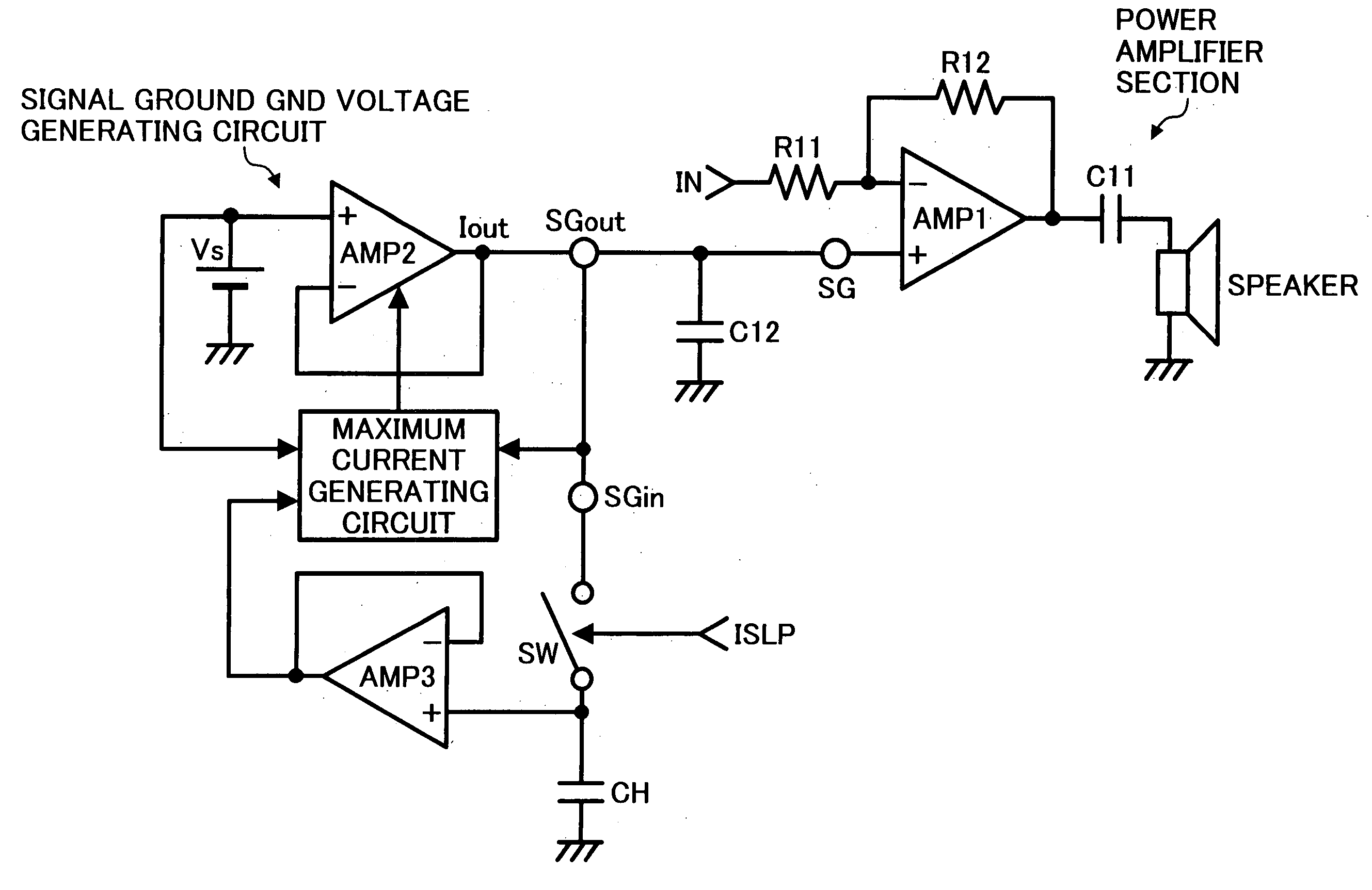
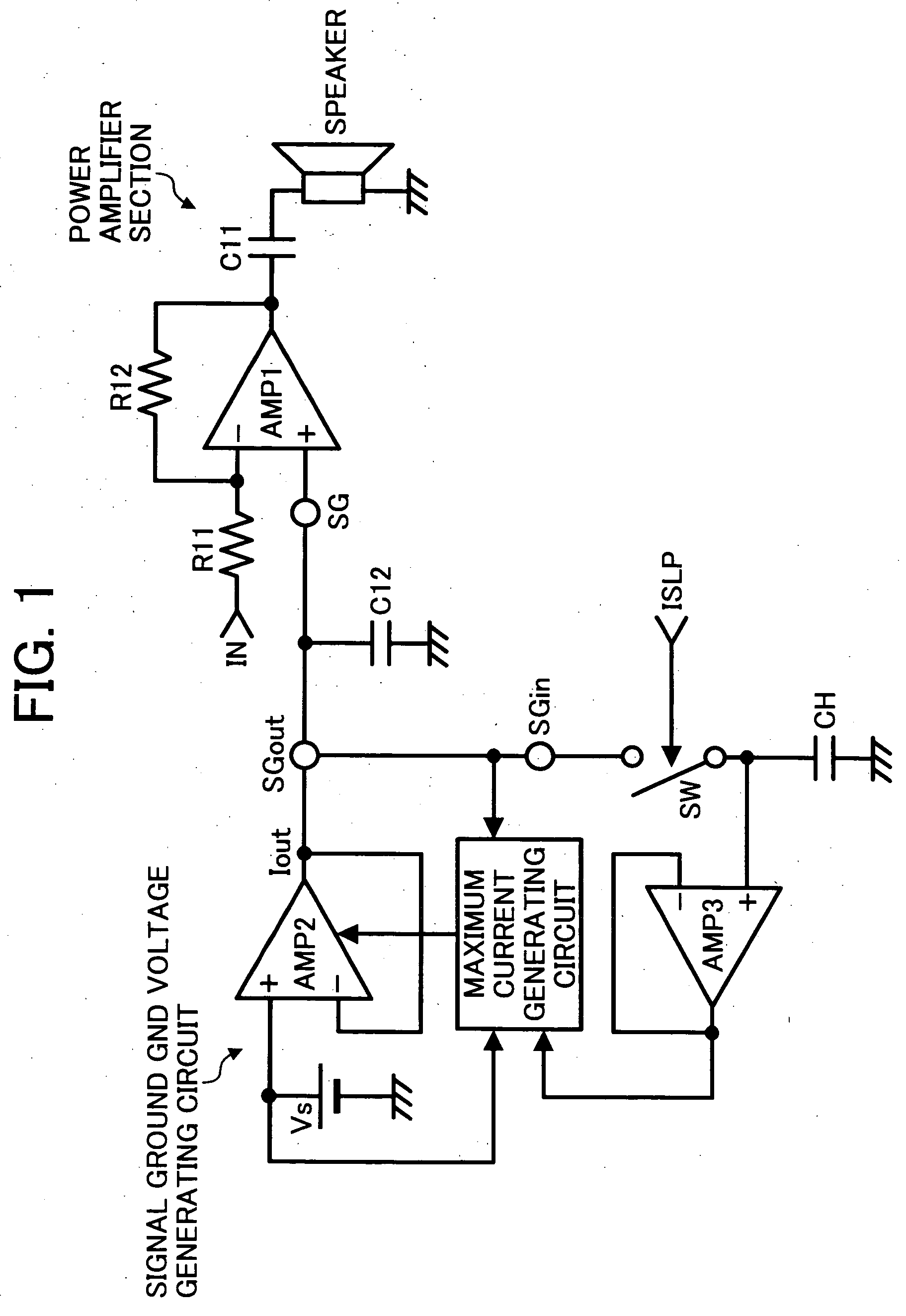
[0035] Referring now to the drawings, wherein like reference numerals designate identical or corresponding parts throughout several views, and in particular to FIG. 1, a pop sound reduction circuit is described below as an exemplary embodiment of the present application. The pop sound reduction circuit includes, but is not limited to, a power amplifier section formed from a power amplifier AMP1 serving as a differential amplifier circuit in its input stage, an input resistor R11 and a feedback resistor 12 which collectively determine a gain, a capacitor C11 that cuts off a direct current, and a speaker. Further included is a signal GND voltage generation circuit section formed from a reference voltage Vs, a voltage follower AMP2, and a maximum current generation circuit that sets the maximum current that the voltage follower AMP2 can output. The maximum current generation circuit includes a sample hold circuit formed from a switching device SW, a hold capacitor CH, and a voltage fol...


PUM


Abstract

An audio power amplifier includes a differential amplifier circuit that serves as an input circuit. The differential amplifier circuit includes a signal ground terminal that receives a signal ground voltage, and an audio signal input terminal that receives an audio signal. A signal ground voltage generation circuit is provided to output the signal ground voltage. The signal ground voltage generation circuit includes a voltage follower amplifier that outputs a current, a reference voltage source that is input to the voltage follower amplifier, and a current control circuit that controls the current output from the voltage follower amplifier. The signal ground voltage rises in a prescribed manner while suppressing a pop sound during its transition.

Description

COPYRIGHT NOTICE [0001] A portion of the disclosure of this patent document contains material which is subject to copyright protection. The copyright owner has no objection to the facsimile reproduction by anyone of the patent document or the patent disclosure, as it appears in the Patent and Trademark Office patent file or records, but otherwise reserves all copyright rights whatsoever. BACKGROUND [0002] 1. Field of the Invention [0003] The present application relates to audio power amplifiers, systems, constant voltage generation circuits, and amplifier circuits for use in a speaker system, and in particular to such audio power amplifiers, systems, constant voltage generation circuits, and amplifier circuits, which employ a pop sound reduction circuit and reduce so called a pop sound likely generated when a power supply is turned on / off or a standby mode is terminated. [0004] 2. Discussion of the Background Art [0005] It is well known that a speaker system sometimes generates a st...

Claims


Application Information

Patent Timeline
IPC IPC(8): H03F1/30H03F1/00H03F99/00
CPCH03F1/305
Inventor HAGINO, KOHICHI
Owner RICOH KK
Why Eureka
Try Eureka