Incubator

a technology of incubator and carbon dioxide gas, which is applied in the field of incubators, can solve the problems of drying gas supply, adversely affecting humidity, and affecting the supply of dried gas, and is likely to be remarkably affected

Active Publication Date: 2005-04-21
PHC HLDG CORP
View PDF5 Cites 55 Cited by
  • Summary
  • Abstract
  • Description
  • Claims
  • Application Information

AI Technical Summary

Benefits of technology

[0025] According to the invention, the incubator (1) comprises an adiabatic box main body (2) having an opening on its front face, an adiabatic door (7) mounted on the adiabatic box main body in an openable and closable manner, a transparent inner door (3) for openably closing the opening, an incubation room (4) surrounded by the inner door (3) and the adiabatic box main body (2) for incubating samples such as cells, microbes and the like, a duct (11) and a circulation blower (14) for causing forced convection of air in the incubation room, a humidifying tray (15) arranged in the duct (11) and at the bottom of the incubation room (4) for storing humidification water (16) for controlling the humidity in the incubation room, and gas supply means (17) for supplying gas for controlling gas concentration in the incubation room, the adiabatic box main body comprising an outer box (21) made of a metal, a

Problems solved by technology

In the case incubating human cells for ectosomatic fertilization or animal fertile eggs as samples, particularly, these samples are likely to be remarkably affe

Method used


Image

  • Incubator
  • Incubator
  • Incubator

Examples


embodiment 1

[0032] (Embodiment 1)

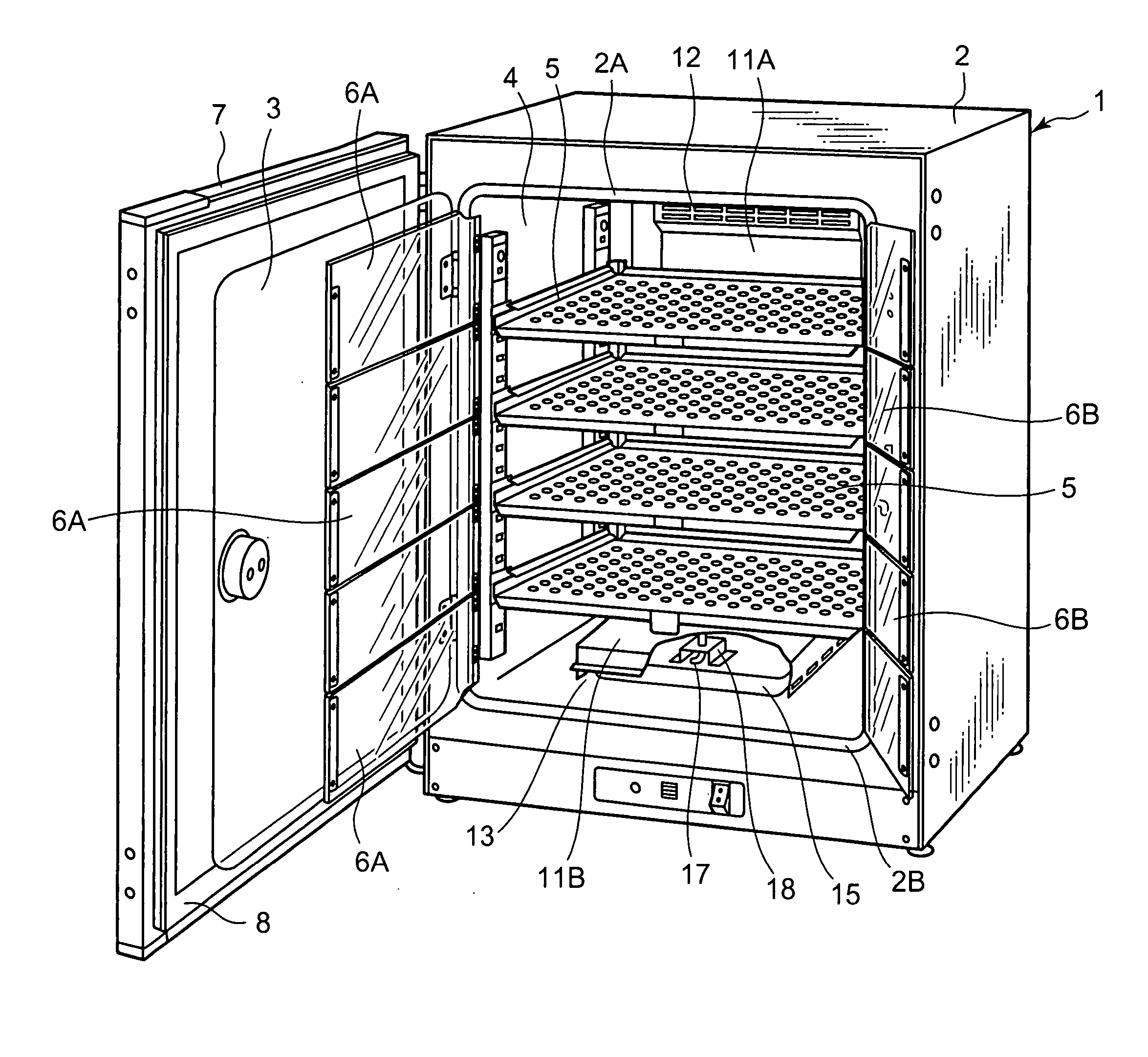
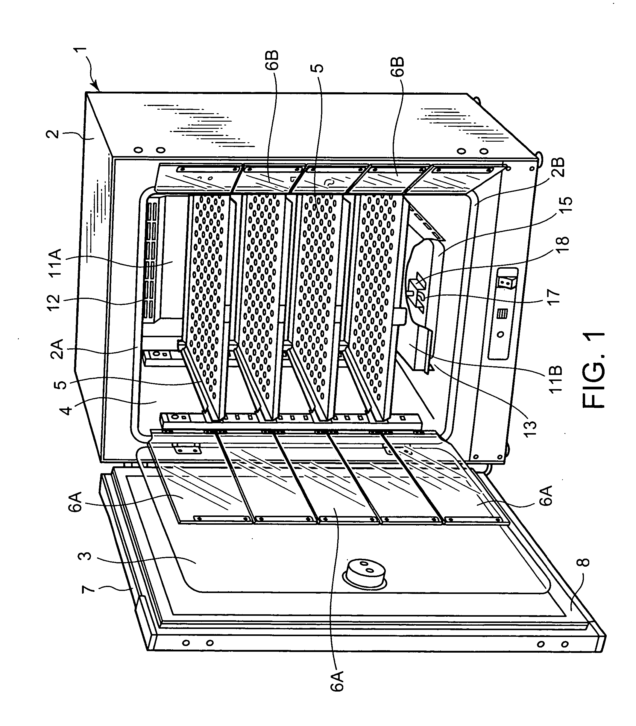
[0033] A multigas incubator 1 as an incubator of the first embodiment of the present invention comprises left hand opening doors (an outer and an inner door in more detail) and smaller doors as biparting doors as shown in FIGS. 1 to 3. An incubation room 4 is formed by a space surrounded by an adiabatic box main body 2 having an opening 2A in its front and a transparent door 3 as the inner door closing the opening 2A in an openable and closable manner. The transparent door 3 is supported at its left end by the adiabatic box main body 2 by means of hinges in an openable and closable manner so that when closed, the opening 2A is air-tightly closed with a gasket 2B provided at the opening of the incubation room 4. The adiabatic box main body 2 is provided with the seal member or gasket 2B along the periphery of the opening 2A of the adiabatic box main body 2 to seal the transparent inner door 3 and the main body 2.

[0034] The inside of the incubation room 4 is divi...

embodiment 2

[0043] (Embodiment 2)

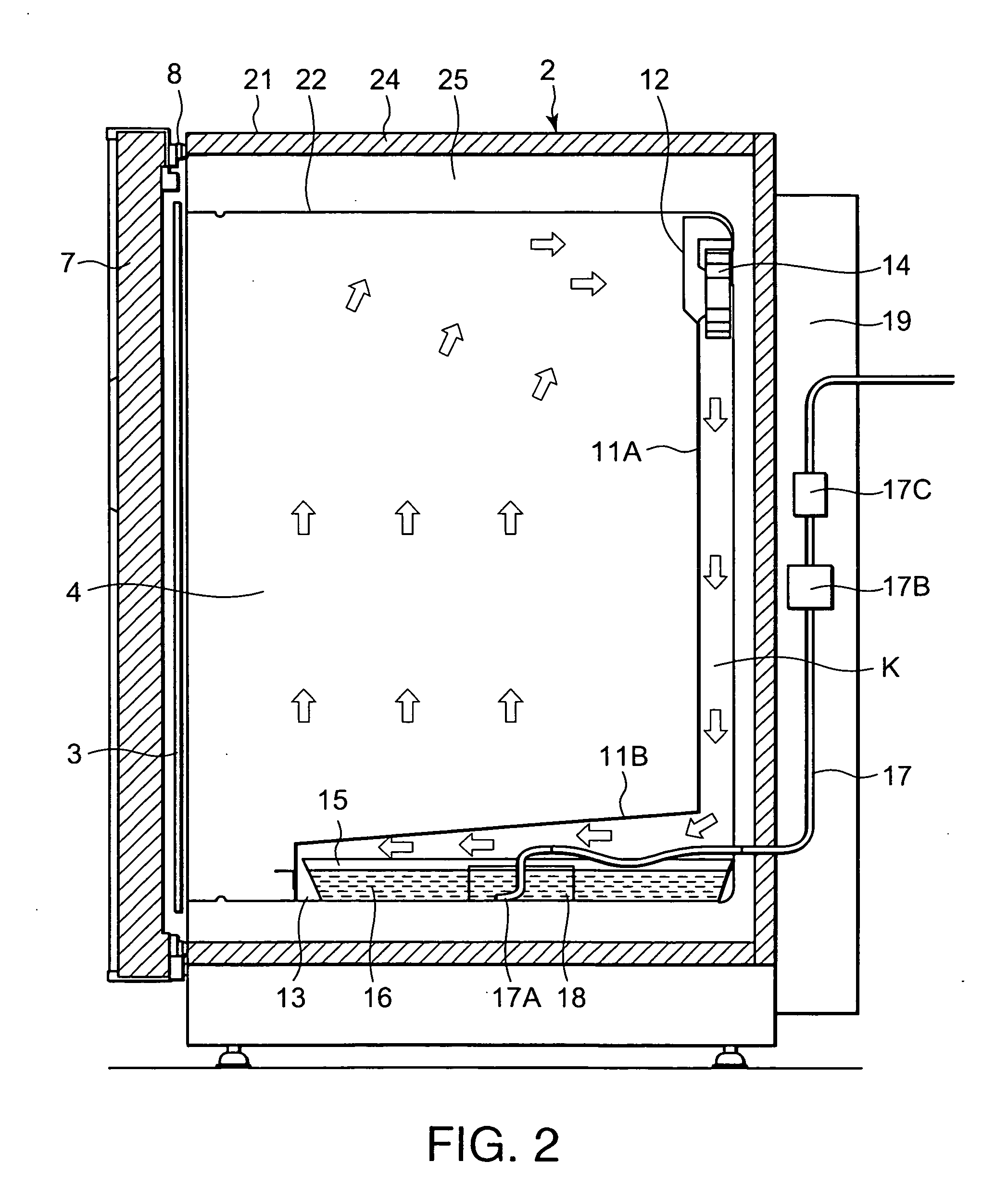
[0044] The second embodiment of the present invention will be explained with reference to FIGS. 3 to 5 hereinafter. A support 18 in the second embodiment of the present invention is so arranged that opposite open ends of the support 18 are arranged in a line in the same direction as the air flowing direction in the air passage K formed by the bottom face duct 11B.

[0045] According to the support 18 in the second embodiment, it forms a passage in the same direction as the air flowing direction formed by the duct 11 so that the humidified gases are conducted with high efficiency in the air flowing direction formed by the circulation blower 14 and the duct 11 leading to the incubation room 4. Accordingly, the spacing between the support 18 and the water surface can be less than the spacing between the water surface and the duct 11 so that the air flow velocity in the space formed by the support 18 and the water surface becomes faster than the air flow velocity in t...


PUM


Abstract

An object of the invention is to provide a multigas incubator capable of shortening humidity-returning time after closing its door. The incubator comprises an adiabatic box main body having an opening on a front face thereof, an adiabatic door mounted on the adiabatic box main body in an openable and closable manner, a transparent inner door for openably closing the opening, and an incubation room surrounded by the inner door and the adiabatic box main body for incubating samples such as cells, microbes and the like. The adiabatic box main body comprises an outer box made of a metal, an inner box made of a metal, a heat insulating material arranged inside the outer box between the outer and inner boxes, and an air layer arranged more inside than the heat insulating material. Gases supplied for controlling concentrations of gases in the incubation room are jetted into humidification water.

Description

BACKGROUND OF THE INVENTION [0001] The present invention relates to a carbon dioxide gas (CO2) incubator or a multigas incubator as an incubator for incubating cultures (samples) such as cells, microbes and the like. [0002] The incubator maintains a temperature and a CO2 concentration constant therein (in incubation room) and keeps its inside in a sterile condition to incubate cultures (samples) such as cells or microbes as incubation targets. Therefore, the inside of the incubator must be periodically processed by sterilization treatment. There has been a multigas incubator provided with a heater and its controller for adjusting the temperature in the incubation room (storing room), gas supply means for supplying and controlling supply gases such as CO2, O2 and the like for controlling concentrations of gases, and a humidifying tray for adjusting the humidity, respectively for the purpose of incubating samples in the incubation room. [0003] On the other hand, as disclosed in Japane...

Claims


Application Information

Patent Timeline
IPC IPC(8): B01L1/00C12M1/38B01L7/00C12M1/00C12M1/12C12M1/14C12M1/36C12M3/00
CPCC12M23/48Y10S435/809C12M41/14C12M1/00C12M3/00C12M1/36C12M1/14
Inventor OSAWA, SHINJIKIKUCHI, YASUHIRO
Owner PHC HLDG CORP
Why Eureka
Try Eureka