Marking system

a marking system and marking technology, applied in the field of marking systems, can solve the problems of limited visibility, lack of durability and portability, and reliance on auxiliary power sources, and achieve the effects of convenient, reliable, and convenient us

Inactive Publication Date: 2005-04-21
BRANCH BANKING & TRUST +2
View PDF10 Cites 39 Cited by
  • Summary
  • Abstract
  • Description
  • Claims
  • Application Information

AI Technical Summary

Benefits of technology

[0015] The present invention provides a marking system that provides a flexible, secure, durable, and inexpensive marker system that allows for remote observations of signatures in multiple segments of the electromagnetic spectrum, such a...

Problems solved by technology

Observation of subjects for any purpose, whether personnel, vehicles, or other objects, presents a challenge in conditions of limited visibility.
One such difficulty is presented when landing an aircraft at a remote location, which process generally requires some marking on the ground to aid the pilot in safely setting the aircraft down.
Problems associated with these earlier marker devices when considering a military application include: i) their reliance on only visual indication of a marked area; ii) their lack of durability and portability; iii) their reliance on an auxiliary power source; and, iv) their limited operational capability due to the necessary fact that they function only under conditions when visible observation is possible.
None of the aforementioned devices provides a marking system effective in sufficiently broad portions of the electromagnetic spectrum (e.g., mid, far, and near infrared regions) and in sufficient modes of operation to provide their operator with sufficient flexibility to meet specific marking needs in varying conditions.
Another difficulty is presented when attempting to calibrate separate vision enhancing systems or devices in their operational environment in envi...

Method used


Image

  • Marking system
  • Marking system
  • Marking system

Examples


Embodiment Construction

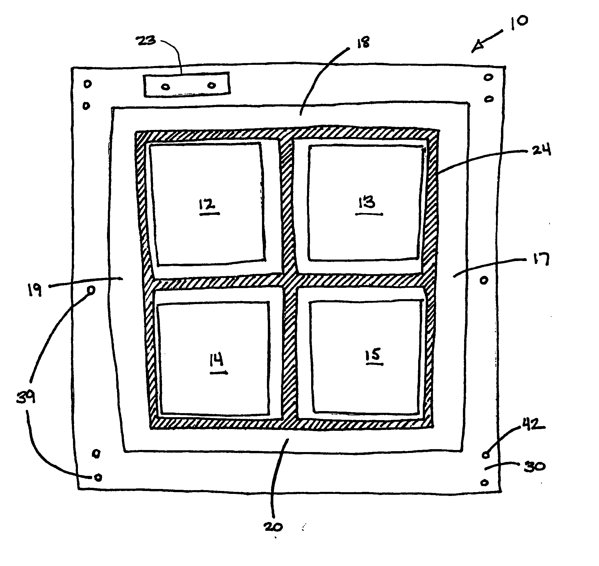
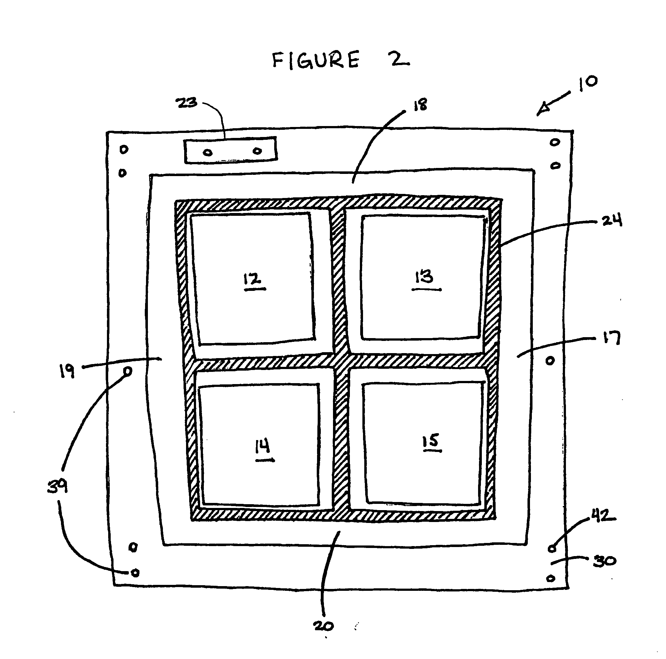
[0038] The invention summarized above and defined by the enumerated claims may be better understood by referring to the following description, which should be read in conjunction with the accompanying drawings in which like reference numbers are used for like parts. This description of an embodiment, set out below to enable one to build and use an implementation of the invention, is not intended to limit the enumerated claims, but to serve as a particular example thereof. Those skilled in the art should appreciate that they may readily use the conception and specific embodiments disclosed as a basis for modifying or designing other methods and systems for carrying out the same purposes of the present invention. Those skilled in the art should also realize that such equivalent assemblies do not depart from the spirit and scope of the invention in its broadest form.

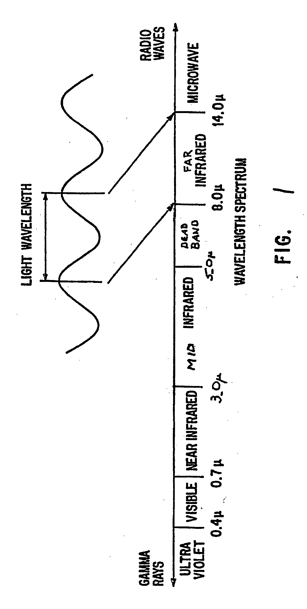
[0039] Referring to FIG. 1, the wavelength of an electromagnetic wave is the characteristic length of a complete cycle o...


PUM


Abstract

A marking system that allows remote observations of visual and infrared electromagnetic signatures emitted from a distinctive marker panel. A kit employing such panels is particularly suitable for military environments, which, in turn, enhances the survivability of military equipment. The marking system preferably provides a signature in the mid and far infrared and near infrared portions of the electromagnetic spectrum, such that the electromagnetic radiation can be observed by a pilot in an approaching moving object such as a plane, helicopter, or land vehicle that is equipped with a thermal imaging system or light intensifier device, even in adverse environmental conditions. In varying embodiments, the marking system may be used as a landing marker, a bore sight panel, and an identification panel. Utilization of passive infrared material enables use of such marking system when external power is unavailable.

Description

CROSS REFERENCE TO RELATED APPLICATION [0001] This application is based upon and claims benefit of copending and co-owned U.S. Provisional Patent Application Ser. No. 60 / 513,090 entitled “Marking System,” filed with the U.S. Patent and Trademark Office on Oct. 21, 2003 by the inventors herein, and copending and co-owned U.S. Provisional Patent Application Ser. No. 60 / 551,927 entitled “Marking System,” filed with the U.S. Patent and Trademark Office on Mar. 10, 2004, the specifications of which are incorporated herein by reference.BACKGROUND OF THE INVENTION [0002] 1. Field of the Invention [0003] This invention relates generally to marking systems for enabling sight and identification of distant geographic locations or items of interest, and more particularly to a marking system having multiple regions of active and / or passive constructions independently observable by artificial vision enhancing devices and optionally the unaided human eye. [0004] 2. Background of the Prior Art [000...

Claims


Application Information

Patent Timeline
IPC IPC(8): B64F1/20G01N37/00
CPCY10T436/13B64F1/20G05D1/0676
Inventor ARMENTROUT, DOUGLAS B.BOYER, THOMAS R.
Owner BRANCH BANKING & TRUST
Why Eureka
Try Eureka