
Golf club head

Inactive Publication Date: 2005-04-21
BRIDGESTONE SPORTS
View PDF29 Cites 31 Cited by
  • Summary
  • Abstract
  • Description
  • Claims
  • Application Information

AI Technical Summary

Benefits of technology

[0011] It is an object of the present invention to solve the above-mentioned problem, and provide a golf club head that has small moment of inertia and an excellent appearance, can be put into or taken out of the caddie bag smoothly, and can make a shot smoothly on the rough. The invention provides a golf club head including a hollow main body; a hosel portion that penetrates through at least one of an upper face of the main body on a heel side and an upper side of a side face of the main body on the heel side, and is integrated with the main body; and a weight member that is provided on the hosel portion at a heel side thereof.
[0023] In the case where the weight member is fixed on both the hosel portion and the heel side of the golf club head main body, vibration of the weight member at a time of shot is prevented or suppressed, and a feeling of hitting becomes better.
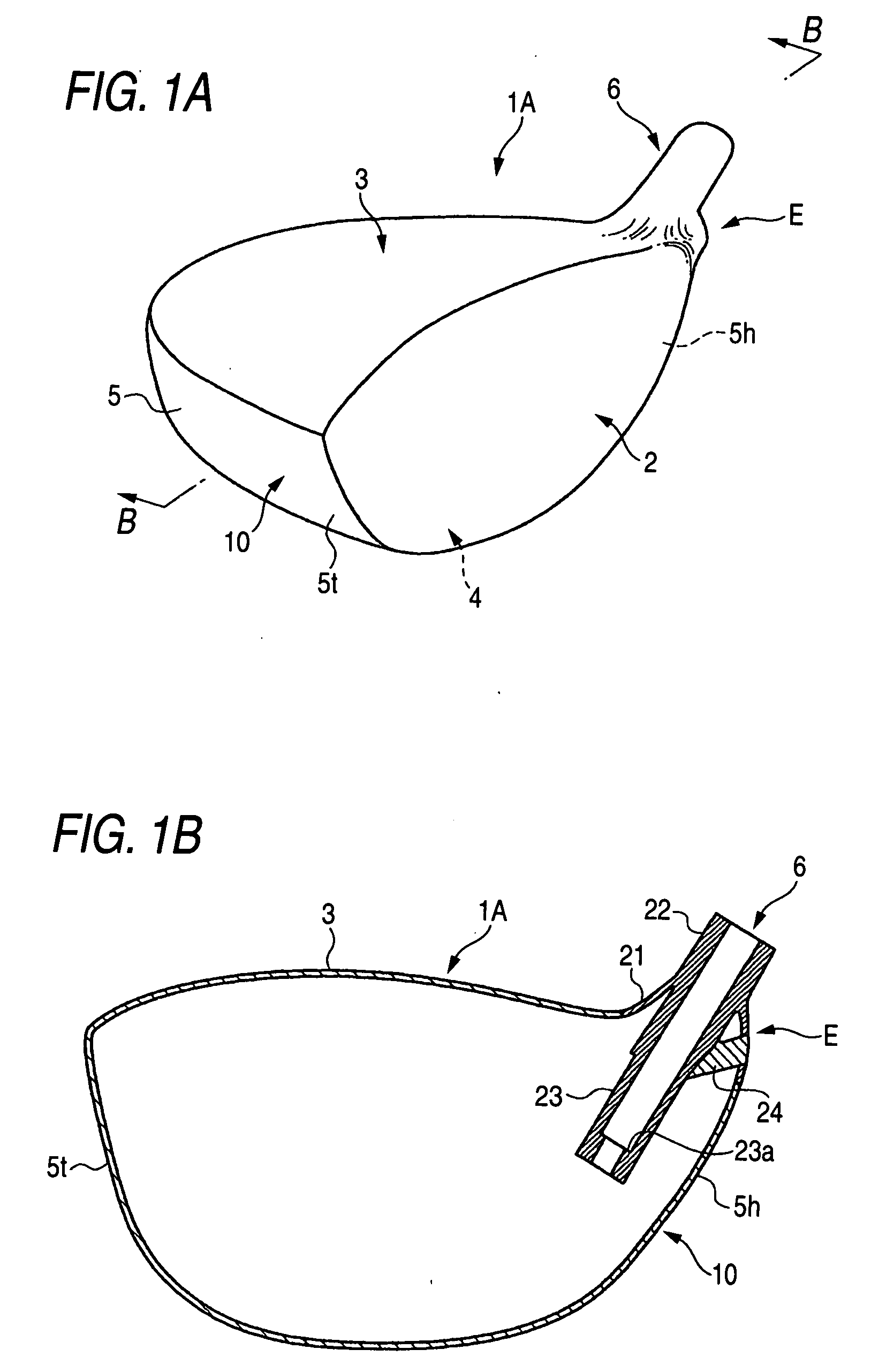
[0026] In the golf club heads of the invention, the weight member is provided on the heel side of the golf club head main body, whereby the head has smaller moment of inertia. Also, since this weight member configures the side face of the head main body, the head is superior in appearance. In the case where the weight member is not protruded from the golf club head, the golf club head can be put into or taken out of the caddie bag smoothly. Moreover, when making a shot on the rough, the head on the heel side does not become tangled with grasses on the rough.
[0028] In the case where the golf club head main body is a metallic cast product, the weight member is a high specific gravity metal, and the weight member is cast into the golf club head main body, the weight member is firmly integrated with the golf club head main body. Thereby, the vibration of the weight member at the time of shot is prevented or suppressed, and the feeling of hitting is better.
[0029] In the case where at least a part of the side face of the golf club head main body on the heel side is made of fiber reinforced plastic having the weight member, it is possible to use a greater amount of the weight member without increasing the weight of the golf club head, because fiber reinforced plastic is light. Therefore, the golf club head is easily designed in terms of the center of gravity.
[0032] In the case where the weight member is made of a metal piece, the metal piece is made thinner, whereby the weight of the golf club head on the heel side is increased without making the thickness on the heel side excessive.

Problems solved by technology

Also, when the golf club is put into or taken out of a caddie bag, the high specific gravity material is likely to be caught on the caddie bag or other clubs.
There is a fear that the high specific gravity material of the hosel portion becomes tangled with grasses so as to cause a miss shot when hitting a ball on a rough.

Method used


Image

  • Golf club head
  • Golf club head
  • Golf club head

Examples


first embodiment

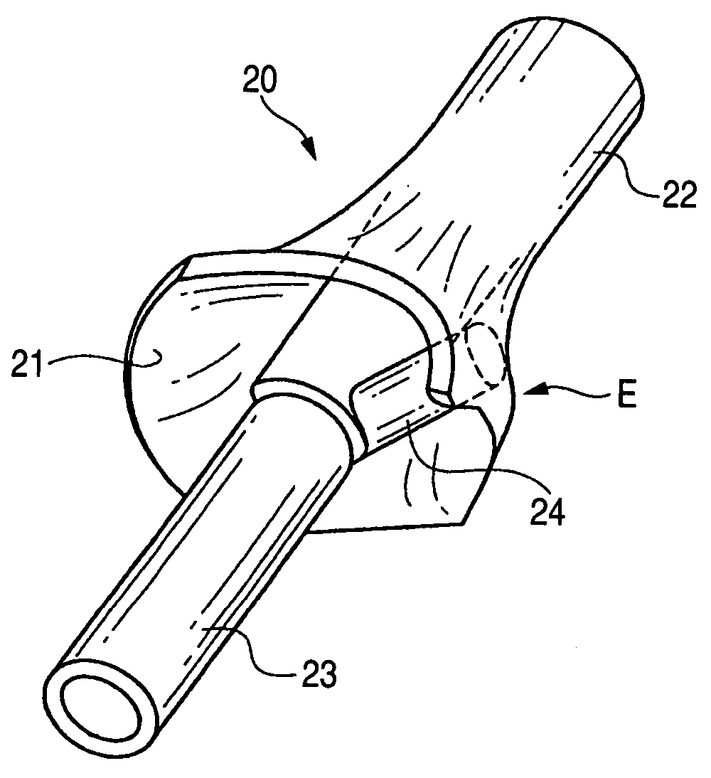
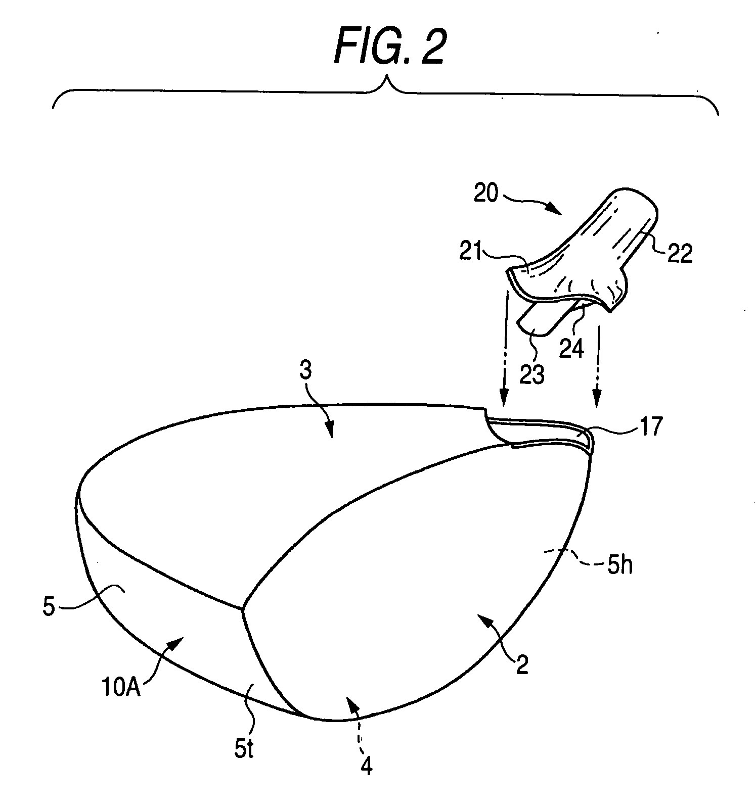
[0047] The preferred embodiments of the present invention will be described below with reference to the accompanying drawings. FIG. 1A is a perspective view of a golf club head according to the invention, and FIG. 1B is a cross-sectional view of the golf club head as shown in FIG. 1A. FIG. 2 is an exploded perspective view of the golf club head. FIG. 3 is a perspective view of a hosel part.

[0048] The golf club head 1A includes a face portion 2, a crown portion 3, a sole portion 4, a side portion 5, and a hosel portion 6. Reference sign 5t denotes a toe side of the side portion 5, and 5h denotes a heel side of the side portion 5. The golf club head 1A is configured with metallic main body parts 10A having a hollow shell shape and a hosel part 20, which are integrated by arc welding, electron beam welding, laser welding or plasma welding.

[0049] A mounting portion 17 for the hosel part 20 is provided on an upper face of the main body parts 10A on the heel side. This mounting portion 1...

second embodiment

[0063] As shown in FIG. 5, a golf club head 1B according to the invention has a barrel portion 26 protruding like a branch from the lower column 23 of a hosel part 20B to the heel side, and the weight material 24 inserted into the barrel portion 26. A top end of the barrel portion 26 on the heel side leads to the skirt portion 21. A lid 27 is disposed to close the weight material 24, and welded to the skirt portion 21.

[0064] The lid 27 is preferably made of pure titanium or titanium alloy, but is not limited thereto.

[0065] Though the lid 27 is employed in FIG. 5, the weight material 24 may be secured by caulking or press fitting, an end face of the weight material 24 being exposed from an outer face of the golf club head 1B. In the case, it is preferred that the end face of the weight material 24 is finished to smoothly continue to the surrounding outer face of the head main body.

third embodiment

[0066] As shown in FIG. 6, a golf club head 1C according to the invention has an overhang portion 28 in which the lower column 23 and the skirt portion 21 on the heel side are continuously integrated, with the weight material 24 held in the overhang portion 28. In the embodiment, a counterbore is provided on a lower face of the overhang portion 28, and the weight material 24 is press fit or caulked into the counterbore. The counterbore is provided on the lower face of the overhang portion 28 in FIG. 6, but may be provided on an outer face of the overhang portion on the heel side.

[0067] The other configuration of the golf club head as shown in FIGS. 5 and 6 is the same as in FIGS. 1 to 3. In these figures, the same numerals or signs designate the same or the same parts.


PUM


Abstract

A weight material is provided on a heel side of a hosel portion in a golf club head. A convex portion E is provided on the heel side of the head. The weight material is disposed within the convex portion. The weight material is made of high specific gravity metal such as tungsten, and welded on both a lower column and a skirt portion.

Description

BACKGROUND OF THE INVENTION [0001] 1. Field of the Invention [0002] The present invention relates to a hollow golf club head, and more particularly to a golf club head (hereinafter simply referred to as a head) of wood type or similar shape. [0003] 2. Description of the Related Art [0004] As the wood type golf club head such as a driver or a fairway wood, hollow and metallic heads are commonly employed. Generally, a hollow golf club head 1 of wood type includes a face portion 2 for hitting a ball, a crown portion 3 configuring an upper face portion of the golf club head, a sole portion 4 configuring a bottom face portion of the golf club head, a side portion 5 configuring a side face portion on a toe side, a back side and a heel side of the golf club head and a hosel portion 6, as shown in FIG. 4. A shaft 7 is inserted into the hosel portion 6 of the golf club head and fixed by adhesives. Recently, many golf club heads called a utility club have appeared on a market. As one kind of ...

Claims


Application Information

Patent Timeline
IPC IPC(8): A63B53/02A63B53/04A63B53/08A63B102/32
CPCA63B53/02A63B53/0466A63B2053/0437A63B2209/023A63B2053/0433A63B2053/0491A63B53/0433A63B53/0437A63B2209/00A63B2209/02A63B60/02A63B2102/32A63B53/04
Inventor NISHITANI, MASAFUMI
Owner BRIDGESTONE SPORTS
Learn More