Cache memory controlling apparatus, information processing apparatus and method for control of cache memory

a control apparatus and cache memory technology, applied in the direction of memory adressing/allocation/relocation, instruments, climate sustainability, etc., can solve the problems of increasing power consumption or reducing processing efficiency

Inactive Publication Date: 2005-04-21
SEIKO EPSON CORP
View PDF6 Cites 60 Cited by
  • Summary
  • Abstract
  • Description
  • Claims
  • Application Information

AI Technical Summary

Problems solved by technology

That is, it is possible to solve the problem such that the number of accesses to unnecessary parts in the cache memory increases, resulting in an increase in power consumption or a reduction in processing efficiency.

Method used


Image

  • Cache memory controlling apparatus, information processing apparatus and method for control of cache memory
  • Cache memory controlling apparatus, information processing apparatus and method for control of cache memory
  • Cache memory controlling apparatus, information processing apparatus and method for control of cache memory

Examples


first embodiment

(First Embodiment)

[0105] First, the configuration will be described.

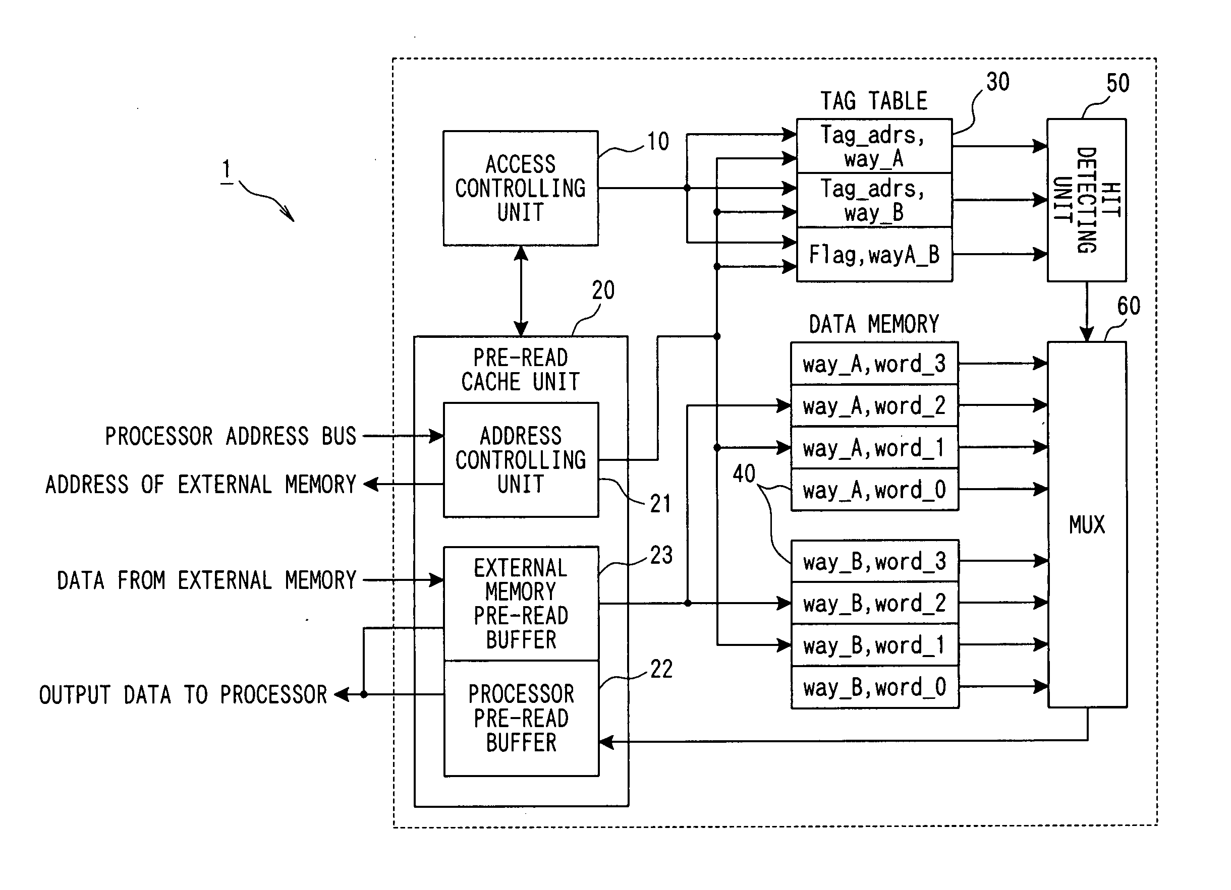
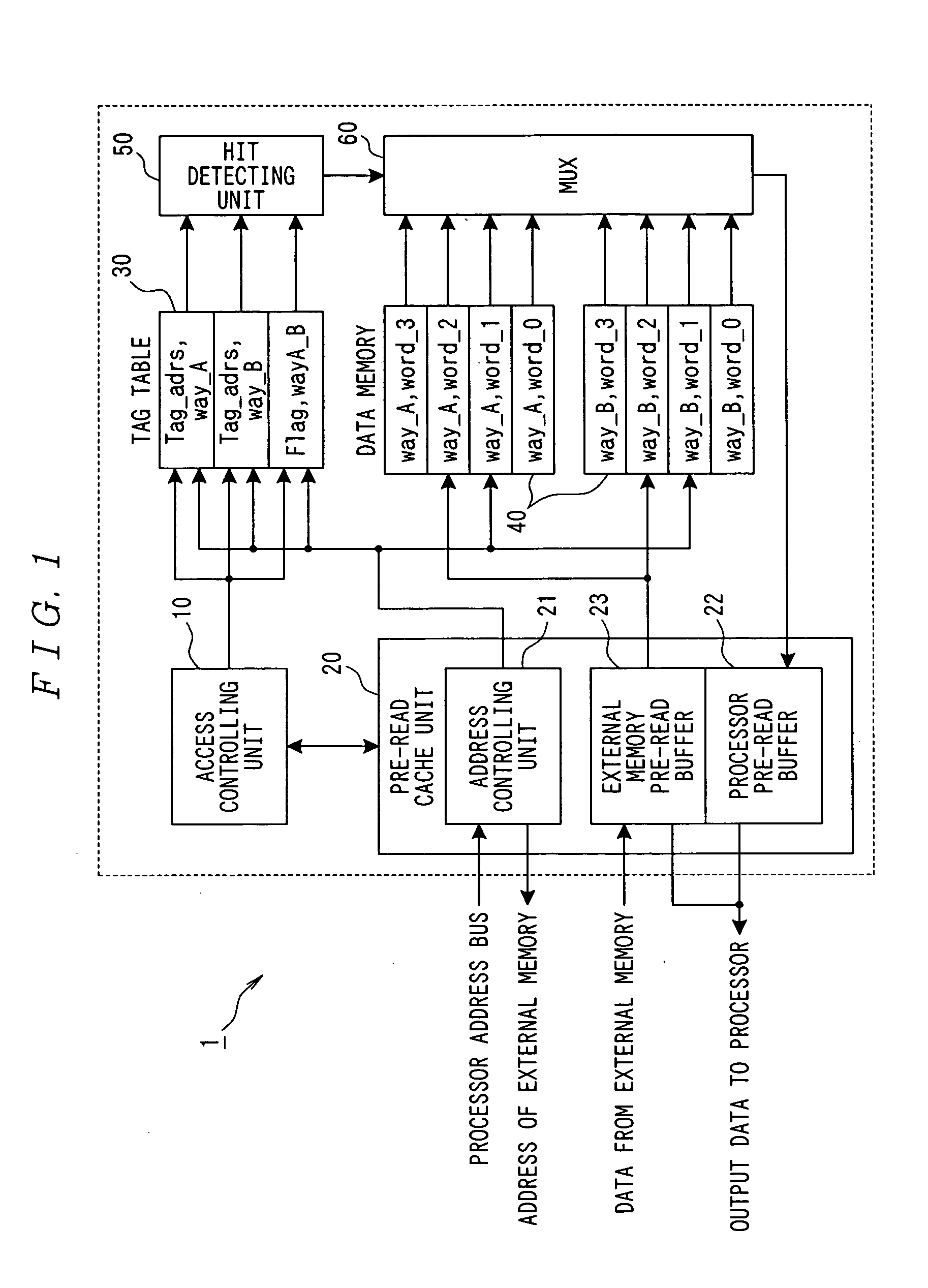
[0106]FIG. 1 shows the configuration of a cache memory controlling apparatus 1 applying the present invention.

[0107] In FIG. 1, the cache memory controlling apparatus 1 comprises an access managing unit 10, a pre-read cache unit 20, a tag table 30, a data memory 40, a hit detecting unit 50 and a MUX 60.

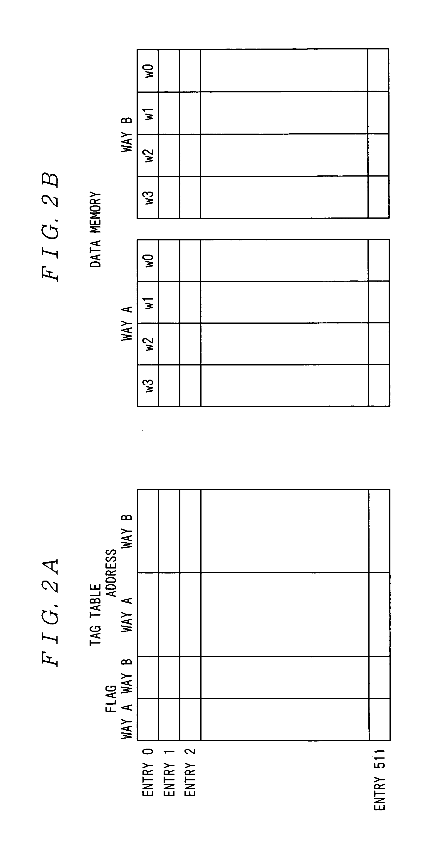
[0108] Furthermore, FIGS. 2A and 2B show the configurations of data stored in the tag table 30 and the data memory 40, wherein FIG. 2A shows the configuration of data in the tag table 30, and FIG. 2B shows the configuration of data in the data memory 40.

[0109] The configuration of the cache memory controlling apparatus 1 will be described below based on FIG. 1, with a reference made to FIGS. 2A and 2B as appropriate. Furthermore, here, it is assumed that the cache memory controlling apparatus 1 is of set associative mode of 2 ways (ways A and B).

[0110] The access managing unit 10 controls the entire cache memory ...

second embodiment

(Second Embodiment)

[0215] The second embodiment of the present invention will now be described.

[0216] In this embodiment, coherency between a cache memory and a memory device can be ensured without executing cache flush by newly providing a write flush mode in addition to a write back mode and a write through mode in a conventional cache memory. Further, in the present invention, the hit rate of a cache and the processing speed can be improved by providing a lock mode.

[0217] First, the configuration will be described.

[0218]FIG. 12 is a schematic diagram showing the configuration of an information processing apparatus 2 applying the present invention.

[0219] In FIG. 12, the information processing apparatus 2 comprises a CPU (Central Processing Unit) core 210, a cache memory 220, a DMAC 230 and memories 240a and 240b, and these parts are connected through a bus.

[0220] The CPU core 210 controls the entire information processing apparatus 2, and executes predetermined programs to ca...


PUM


Abstract

Processing in a cache memory is made appropriate. A cache memory controlling apparatus 1 detects whether data expected to be read subsequently is cached or not while data to be read is read from a processor. If the data to be read subsequently is stored in a cache, the data is stored in a pre-read cache unit 20, and if the data to be read subsequently is not stored in the cache, the data is read from an external memory and stored in the pre-read cache unit 20. Thereafter, if an address of data actually read from the processor in a subsequent cycle matches an address of data stored in the pre-read cache unit 20, the data is outputted from the pre-read cache unit 20 to the processor.

Description

BACKGROUND OF THE INVENTION [0001] 1. Field of the Invention [0002] The present invention relates to an apparatus controlling a cache memory provided for efficiently transferring data between a processor and a memory device, an information processing apparatus comprising the cache memory, and a method for control of the cache memory. [0003] 2. Description of the Related Art [0004] Cache memories have been used for enhancing the speed of processing for reading data on a memory device such as a main memory by a processor. [0005] The cache memory is comprised of memory elements enabling data to be read at a high speed by the processor. The cache memory stores part of data stored in the memory device (hereinafter referred to as “memory device data” as appropriate), and when the processor reads data from the memory device, the data is read from the cache memory if the data is stored in the cache memory, whereby data can be read at a high speed. [0006] There are various modes for the cach...

Claims


Application Information

Patent Timeline
Patent Type & Authority Applications(United States)
IPC IPC(8): G06F12/00G06F12/08
CPCY02B60/1225G06F12/0862Y02D10/00
Inventor TODOROKI, AKINARI
Owner SEIKO EPSON CORP
Why Eureka
Try Eureka