Reusable vacuum bag and methods of its use

a vacuum bag and reusable technology, applied in the field of reusable vacuum bags, can solve the problems of large cost, limited and infrequent use by most commercial establishments, and easy attack of silicone bags, and achieve the effects of reducing disposables and costs, reducing the risk of contamination, and maintaining some flexibility

Inactive Publication Date: 2005-04-28
SAINT GOBAIN BRUNSWICK TECH +1
View PDF28 Cites 127 Cited by
  • Summary
  • Abstract
  • Description
  • Claims
  • Application Information

AI Technical Summary

Benefits of technology

[0009] In the preferred processes of this invention, the vacuum bags can be used to substitute for three-dimensional un-reinforced silicone vacuum bags. They can further include resin flow channels, vacuum exhaust parts and other features to eliminate disposables and expense.
[0010] In a further embodiment of this invention, a three-dimensional bag is provided which can be fitted tightly during the molding of a composite molded part while maintaining some flexibility so as to avoid fiber “bridging”. The vacuum bags of this invention can have as many seams as necessary, or none at all, to have a tailored bag fit for the molded part. The bag can withstand multiple cycles of a full vacuum, for example, of at least one bar, without leaking. The vacuum bags of this invention can be sealed to female molds to preserve a vacuum with the standard flange “tacky” tape, or soft silicone, or other reusable rubber seals that can be bonded to the inner surface of the vacuum bag with structural adhesives.
[0011] In one aspect of the present invention, the vacuum bags of this invention surface release from the cured thermoset or solidified thermoplastic resin parts in the final composite construction. This has the advantage of eliminating a release layer disposable used in the molding process.
[0012] In a further detailed embodiment of the present invention, the vacuum bag can have a bumpy surface, channels, ridges, mesh, or conduits strategically located to be used as part of a resin feed channel or vacuum exhaust port. The vacuum bags of this invention may also have different layers, materials or regions that could allow certain sections to be semi-rigid (relatively thick or stiff panels) while other areas may be thinner, or made of more pliable or of stretchable fabric materials, to allow the bag to fit tightly into small radiuses or around sharp corners. In still further embodiments of the present invention, a vacuum bag is provided which is essentially a double layer bag with baffles built into it so hot air or vapors could be pumped between the two layers to help cure thermosetting composites faster. This baffle system will also have the ability to carry cold water / air that can be used to rapidly cool the composite part once the resin's curing peak exotherm temperature has been reached, reducing the in-mold cycle times for the molding. This can be provided, for example, by using a stiffer bumpy fabric on the inside surface of the outer layer with a thin pliable inner layer that can be vacuum pressed together to create a double bumpy or undulated surface, or by using a more flexible film bonded to an open mesh-type or scrim fabric.

Problems solved by technology

Permanent rubber bags, such as silicone or synthetic rubber have been used by some fabricators, but their high initial cost and handling and storage requirements result in limited and infrequent use by most commercial establishments.
Silicone bags are also readily attacked by resin systems used to mold parts.
In some cases, artisans have been known to add PTFE films to help overcome resin degradation of silicone bags, but this has been at great cost.
If bridging occurs, the bag may rupture at high temperature and pressure causing the loss of the part.
The necessity of having both a polymeric vacuum bag film and an additional nonstick release film, as well as a chemical mold release, adds to the cost of bagging operations generally, and resin transfer molding operations in particular.

Method used


Image

  • Reusable vacuum bag and methods of its use
  • Reusable vacuum bag and methods of its use
  • Reusable vacuum bag and methods of its use

Examples


example a

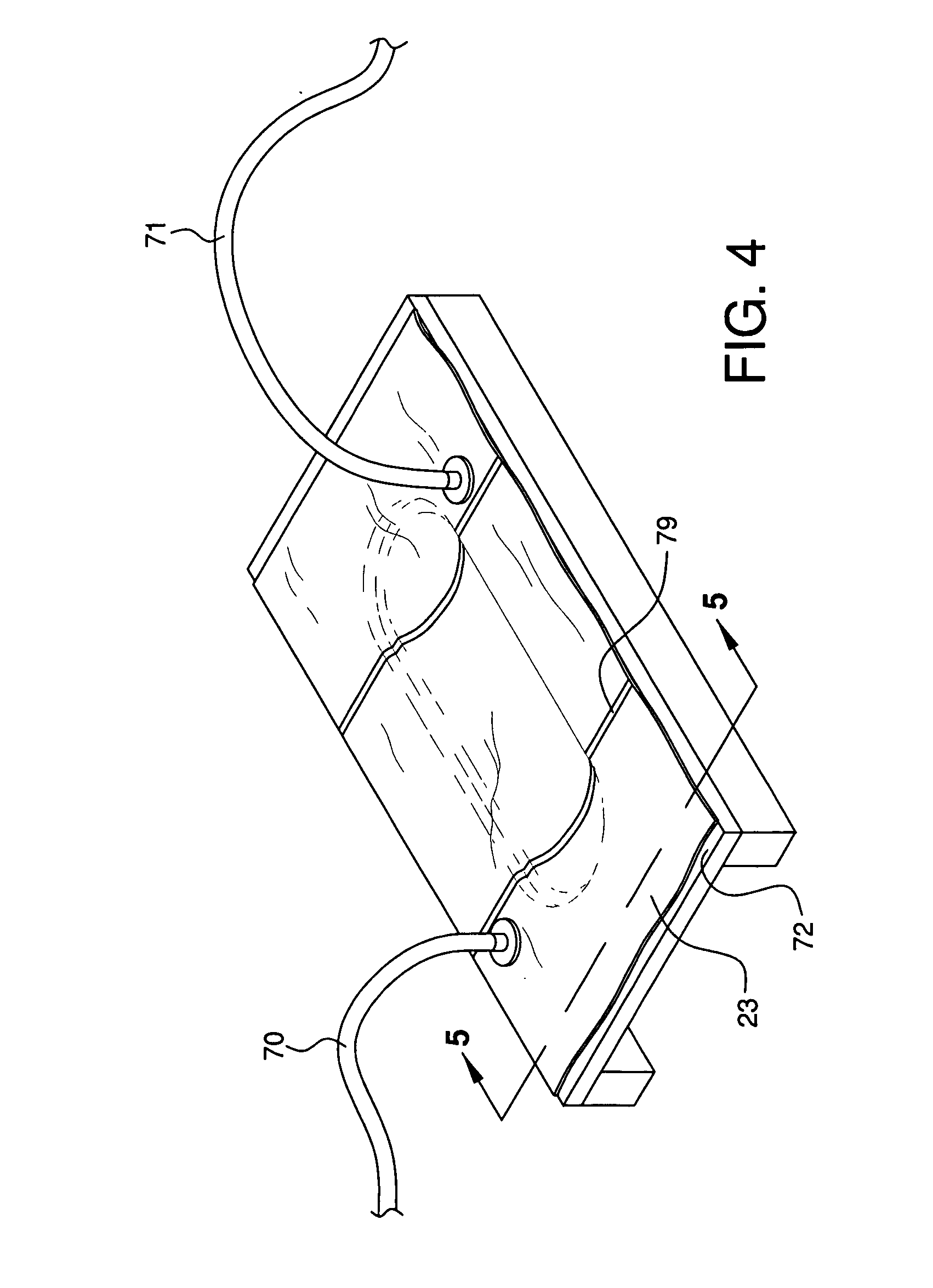
[0068] With respect to FIGS. 4 and 5, an example of preferred resin transfer molding operation using the reusable vacuum bag 23 of this invention is described. The bag 23 can be made of a 3.5 oz / yd2 plain weave, woven Kevlar® fabric with a multi-layered PTFE / FEP coated resin film thermally bonded to, and / or melted into, one or both surfaces of the woven fabric. This base fabric is a Saint-Gobain Performance Plastics, Merrimack, N.H., fabric style “X-22 Natural”, that we had developed for the prototype vacuum bags. This is just one of the many fabrics useful for this application. The resin and catalyst may be mixed just prior to introduction into the envelope formed between the vacuum bag 23 and the mold 72. The catalyst can include a conventional heat reactive or ambient temperature reactive catalyst or any conventional photoinitiator and / or photosensitizer, depending upon the dynamics of the thermosetting system. Alternatively, a melted thermoplastic material could be employed. The...


PUM

PropertyMeasurementUnit
thicknessaaaaaaaaaa
pressure dropaaaaaaaaaa
temperaturesaaaaaaaaaa

Abstract

Reusable vacuum bags are provided which include a fabric layer containing reinforcement fibers and a release surface disposed on at least the first side of the fabric layer. The vacuum bag is capable of withstanding multiple mold cycles of the vacuum of less than ambient pressure without significant leakage. In addition, the described vacuum bag can be used in resin transfer molding and standard bagging operations with commercial benefit.

Description

FIELD OF THE INVENTION [0001] The present invention relates to a reusable vacuum bag for forming polymeric materials, and especially to reusable bags or membranes for use in resin transfer molding and bagging operations. BACKGROUND OF THE INVENTION [0002] Vacuum bag techniques are well known in the art of making large composites, such as those used in the manufacture of industrial containers and boats. They can involve both dry lay-up and wet lay-up processes. After the fiber reinforcement is laid up on a forming tool or mold surface, a flexible gas impervious sheet, liner, membrane or bag (hereinafter “bag”), is used to form a sealed vacuum envelope over the lay-up. A heat, ambient temperature or light curable catalyzed resin in liquid form is then introduced into the envelope and a vacuum is drawn on the interior envelope space. The vacuum induces an internal collapse of the film envelope against the mold surface and fiber reinforcement so that the resin and reinforcement follow t...

Claims


Application Information

Patent Timeline
Patent Type & Authority Applications(United States)
IPC IPC(8): B01D46/02B29C70/44
CPCB29C43/12B29C2043/3644B29C70/443Y10T442/3878B29C70/544
Inventor CARON, MARK C.
Owner SAINT GOBAIN BRUNSWICK TECH
Why Eureka
Try Eureka