
Fine die cast metallic parts

Inactive Publication Date: 2005-04-28
TAKATA CORPORATION
View PDF4 Cites 8 Cited by
  • Summary
  • Abstract
  • Description
  • Claims
  • Application Information

AI Technical Summary

Benefits of technology

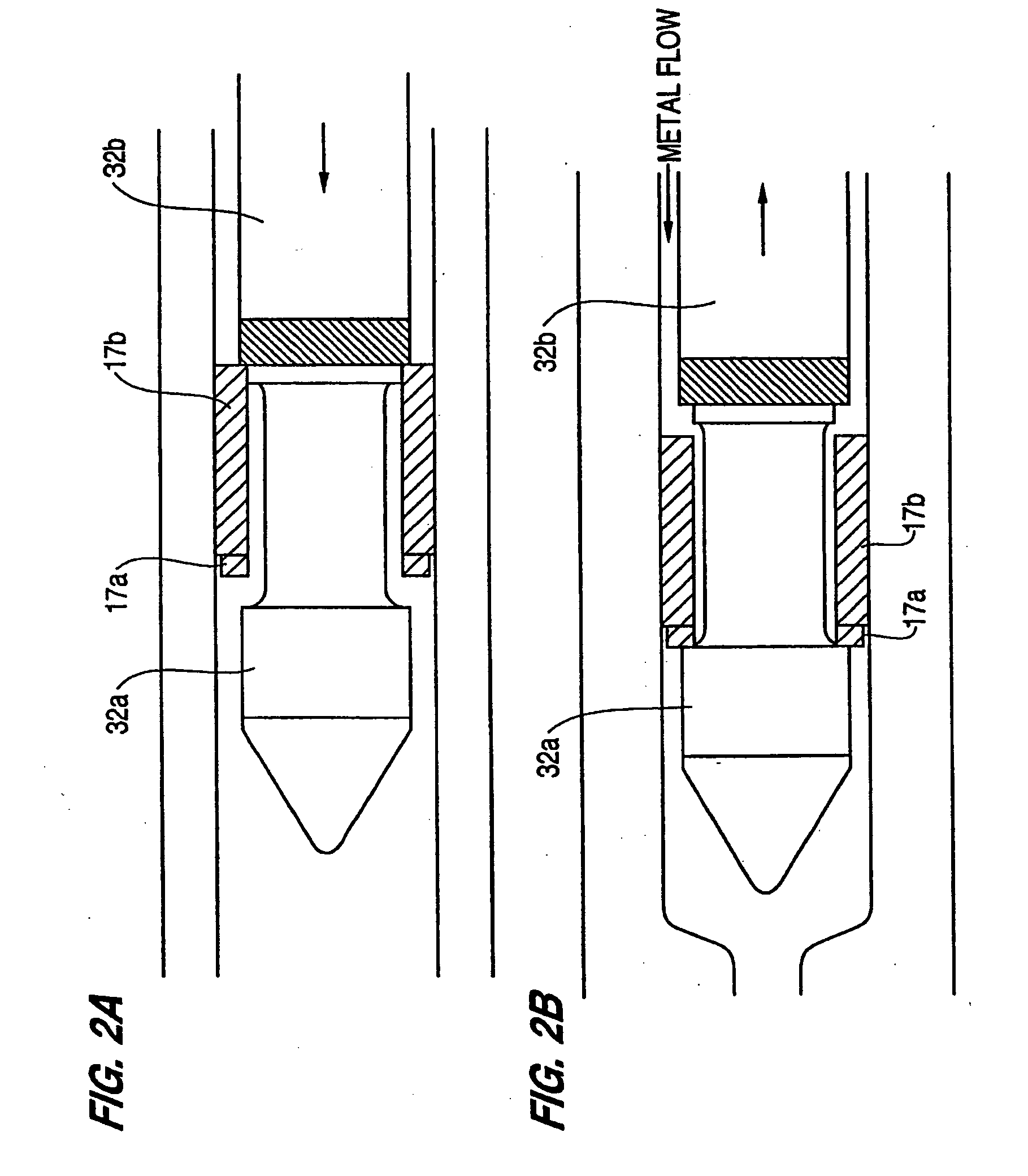
[0014] Still another object of the invention is to provide metallic parts made using an injection molding system that minimizes the amount of gas trapped in liquid metal prior to its injection into the mold.
[0025] Because the molded metallic parts according to the present invention can be molded to have such fine dimensions and smooth surfaces, it is possible to mold indented and protruding surface features onto the surface of the molded metallic parts without having to apply subsequent machining, milling, engraving, or sanding to the surface feature to obtain an acceptably finished surface. According to prior art methods, however, molded metallic parts can not be molded with such fine dimensions-and smooth surfaces. Consequently, prior art molded metallic parts must be machined, milled, engraved, sanded, or otherwise finished after being molded in order to obtain an acceptably finished surface. Molded metallic parts according to the present invention are superior in that the additional time consuming and expensive milling / finishing operation is not required.

Problems solved by technology

Molded metallic parts having low densities are not generally desirable because of their reduced mechanical strength, higher porosity, and larger micro shrinkage.
It is thus difficult to accurately dimension conventional molded metallic parts and, once dimensioned, to maintain their shapes.
Moreover, molded metallic parts produced from conventional die casting have difficulty in reducing the resilient stresses developed therein.
It is difficult to accurately control all of the process parameters within a single cylindrical housing, especially temperature, shot volume, pressure, time, etc., and as a result, molded metallic parts of inconsistent characteristics are produced.
As a consequence, if a molded metallic part of undesired characteristics is produced by its system, recycling of the defective part is not possible unless the defective part is first recast in pellet form.
Furthermore, metal parts made from metal in the thixotropic state which is injected into a mold may have an uneven surface.

Method used


Image

  • Fine die cast metallic parts
  • Fine die cast metallic parts
  • Fine die cast metallic parts

Examples


Embodiment Construction

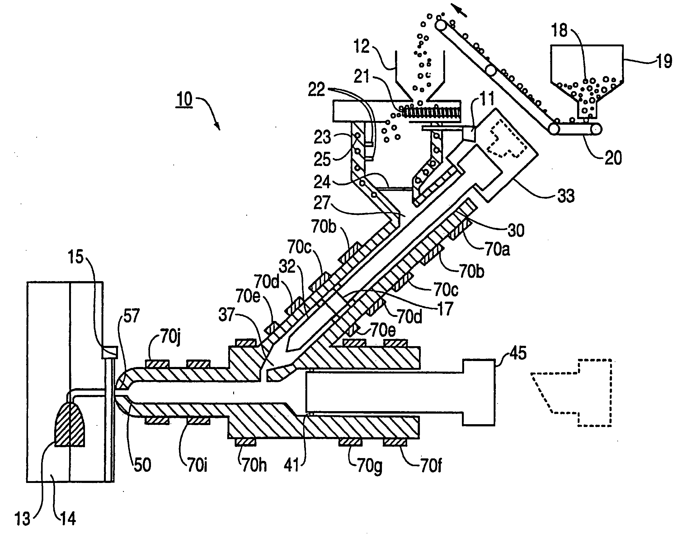
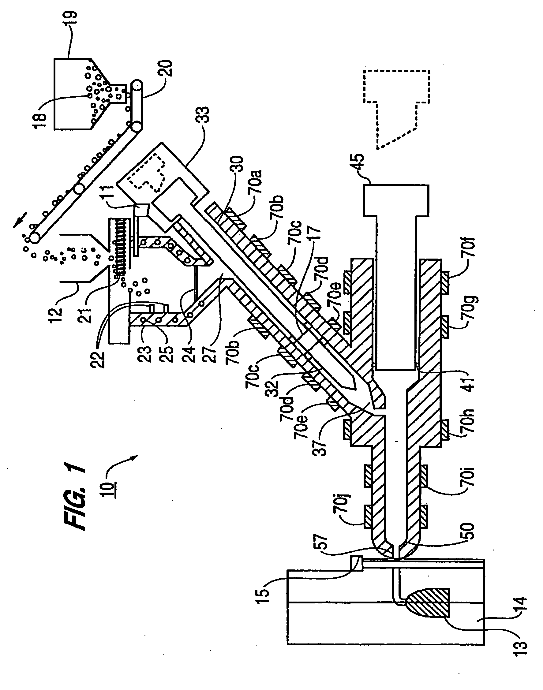
[0056] In the discussion of the preferred embodiment which follows, a metal alloy is produced by injection molding from a magnesium (Mg) alloy ingot or pellets which are melted and processed in a liquid state. However, the invention is not limited to magnesium products and is equally applicable to other types of materials, metals and metal alloys.

[0057] The terms “melted metal” and “melted material” as used herein encompasses metals, metal alloys and other materials which can be converted to a liquid state and processed in an injection molding system. A wide range of such metals is potentially useful in this invention, including aluminum (Al), Al alloys, zinc (Zn), Zn alloys, and the like.

[0058] Unless otherwise indicated, the terms “a” or “an” refer to one or more. Unless otherwise indicated, the term “gas” refers to any gas (including air) that can be present in the injection chamber at start-up or that is trapped in the injection chamber and forced out during operation of the i...


PUM

PropertyMeasurementUnit
Thicknessaaaaaaaaaa
Thicknessaaaaaaaaaa
Lengthaaaaaaaaaa

Abstract

A finished molded metal part is produced by an injection molding system includes a feeder in which a metal is melted and a first chamber into which a desired amount of melted metal is introduced. The molded metal parts can have extremely fine dimensions, small thicknesses, and indented or protruding surface features that are molded with such low porosity that no further milling / finishing operation is required before the part is used in its finished state.

Description

CROSS-REFERENCE OF THE RELATED APPLICATION [0001] This application is a continuation-in-part of application Ser. No. 09 / 160,330, filed on Sep. 25, 1998, titled “Method And Apparatus For Manufacturing Metallic Parts by Injection Molding From the Semi-Solid State”; application Ser. No. 09 / 160,976, also filed on Sep. 25, 1998, titled “Method and Apparatus for Manufacturing Metallic Parts by Fine Die Casting” which issued as U.S. Pat. No. 5,983,976, on Nov. 16, 1999, and provisional application Ser. No. 06 / 080,078, filed Mar. 31, 1998, the disclosures of which are hereby incorporated by reference into this application in their entirety.BACKGROUND OF THE INVENTION [0002] 1. Field of the Invention [0003] The invention relates to fine die cast metallic parts, more particularly to fine die cast metallic parts produced by a process involving injection of a melted metal into a mold. [0004] 2. Description of the Related Art [0005] One conventional method used to produce molded metallic parts f...

Claims


Application Information

Patent Timeline
IPC IPC(8): B22D17/00B22D17/30B29C45/53
CPCB22D17/007B29C45/53B22D17/30
Inventor KONO, KANAME
Owner TAKATA CORPORATION
Learn More