
Depth of interaction detector with uniform pulse-height

a detector and pulse-height technology, applied in the direction of radiation intensity measurement, instruments, x/gamma/cosmic radiation measurement, etc., can solve the problems of non-uniform image, damage to overall depth of interaction detection characteristics and energy-resolving characteristics of the device, and achieve the effect of improving the uniformity of energy information

Active Publication Date: 2005-04-28
HAMAMATSU PHOTONICS KK +1
View PDF7 Cites 35 Cited by
  • Summary
  • Abstract
  • Description
  • Claims
  • Application Information

AI Technical Summary

Benefits of technology

[0008] Accordingly, it is an object of the present invention to provide a depth of interaction detector with uniform pulse-height as a radiation detector, which receives light rays on the end of a scintillator having a long and narrow shape and which is improved in the uniformity of energy information and position or depth of interaction information generated due to the dependence of the quantity of light received upon the distance between the light-emitting position (a light-emitting scintillator cell) and the light-receiving element.
[0009] It is a further object of the present invention to provide a depth of interaction detector with uniform pulse-height as a radiation detector, in which the difference in light collection efficiency between scintillator cells is reduced and the optical output of the light-receiving element is high even when radiation is absorbed by and emitted from a scintillator layer positioned above the scintillator layer optically coupled to the light-receiving element.
[0010] It is a still further object of the present invention to provide a depth of interaction detector with uniform pulse-height having a three-dimensional depth of interaction-detecting function and an energy information acquisition function independent of which scintillator cell practically emits light rays. The detector is excellent in the energy resolution capacity, it can provide, even when radiation is absorbed by and emitted from a scintillator layer positioned above the scintillator layer optically coupled to the light-receiving element, precise detected information with respect to the energy-position (or depth of interaction) with an accuracy identical to that observed for the lower part of the scintillator layers of the detector and it thus permits any compact arrangement of scintillator cells along the periphery of a torus.
[0011] It is a still another object of the present invention to provide a depth of interaction detector with uniform pulse-height, which is never accompanied by any deterioration of abilities of resolving energy, position (or depth of interaction) and time, unlike the optical attenuation technique such as those conventionally used.

Problems solved by technology

This not only complicates the structure of such a signal-processing circuit for a multi-layer scintillation block obtained by stacking up scintillator cells, but also suffers from a problem in that images thus obtained are non-uniform because the energy resolution capacity of the scintillator cells differ from one another.
In other words, there is observed, for scintillator cells located far away from a light-receiving element, a decrease of the sum of output signals due to such stacking up of the scintillator layers and accordingly, the overall depth of interaction-detecting characteristics and energy-resolving characteristics of the device would be damaged.
Thus, the conventional detector would require the use of an amplifier having a wide dynamic range and a digital processing ability upon the processing of signals output from the detector and this makes the design of a front-end processing circuit difficult.
However, this method suffers from a problem such that all of the abilities of resolving energy, position (depth of interaction) and time are deteriorated because of the reduction of the quantity of light capable of being utilized by the light-receiving element.

Method used


Image

  • Depth of interaction detector with uniform pulse-height
  • Depth of interaction detector with uniform pulse-height
  • Depth of interaction detector with uniform pulse-height

Examples


example

[0045] The present invention will hereunder be described in more detail with reference to the accompanying drawings.

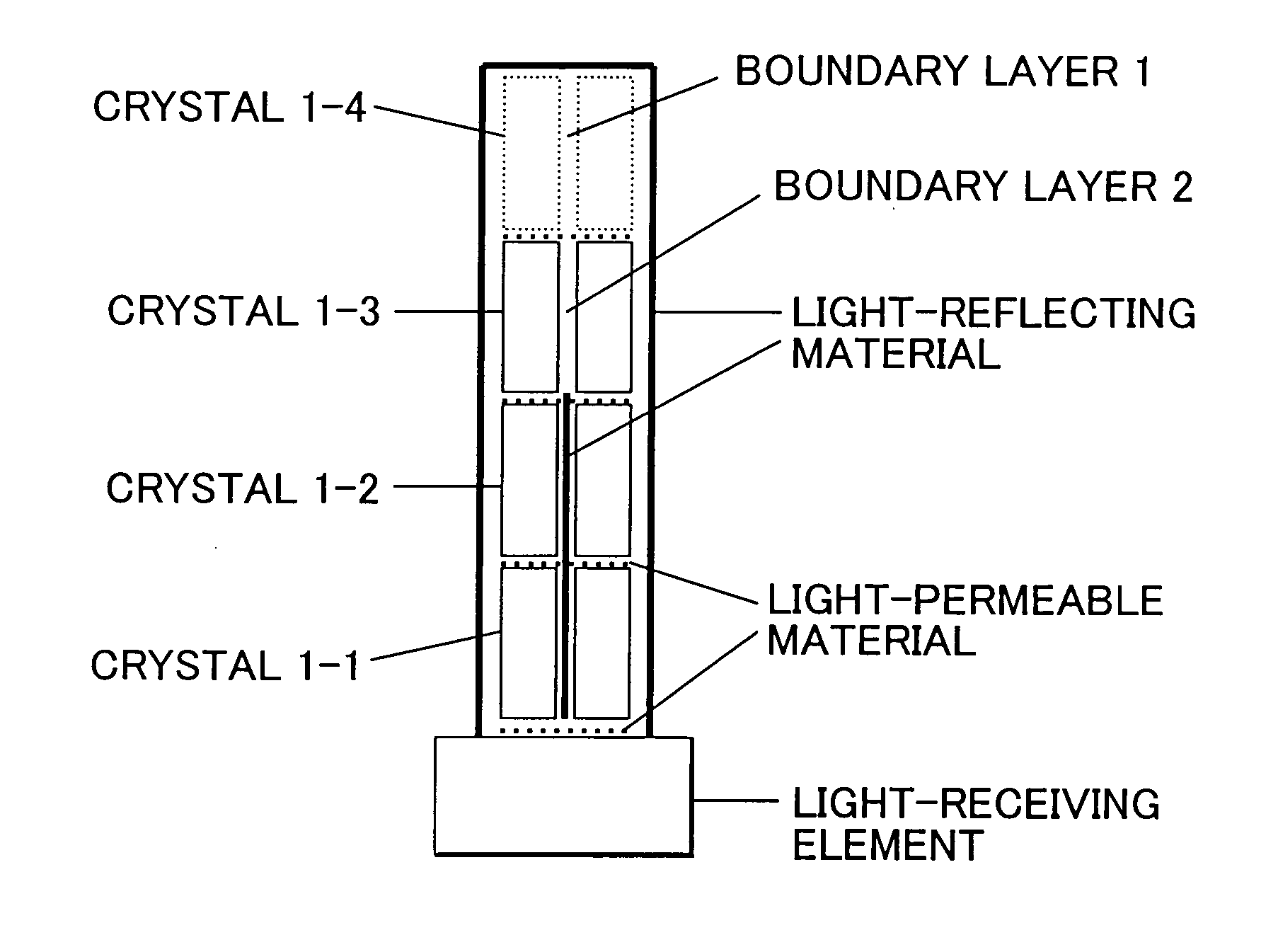
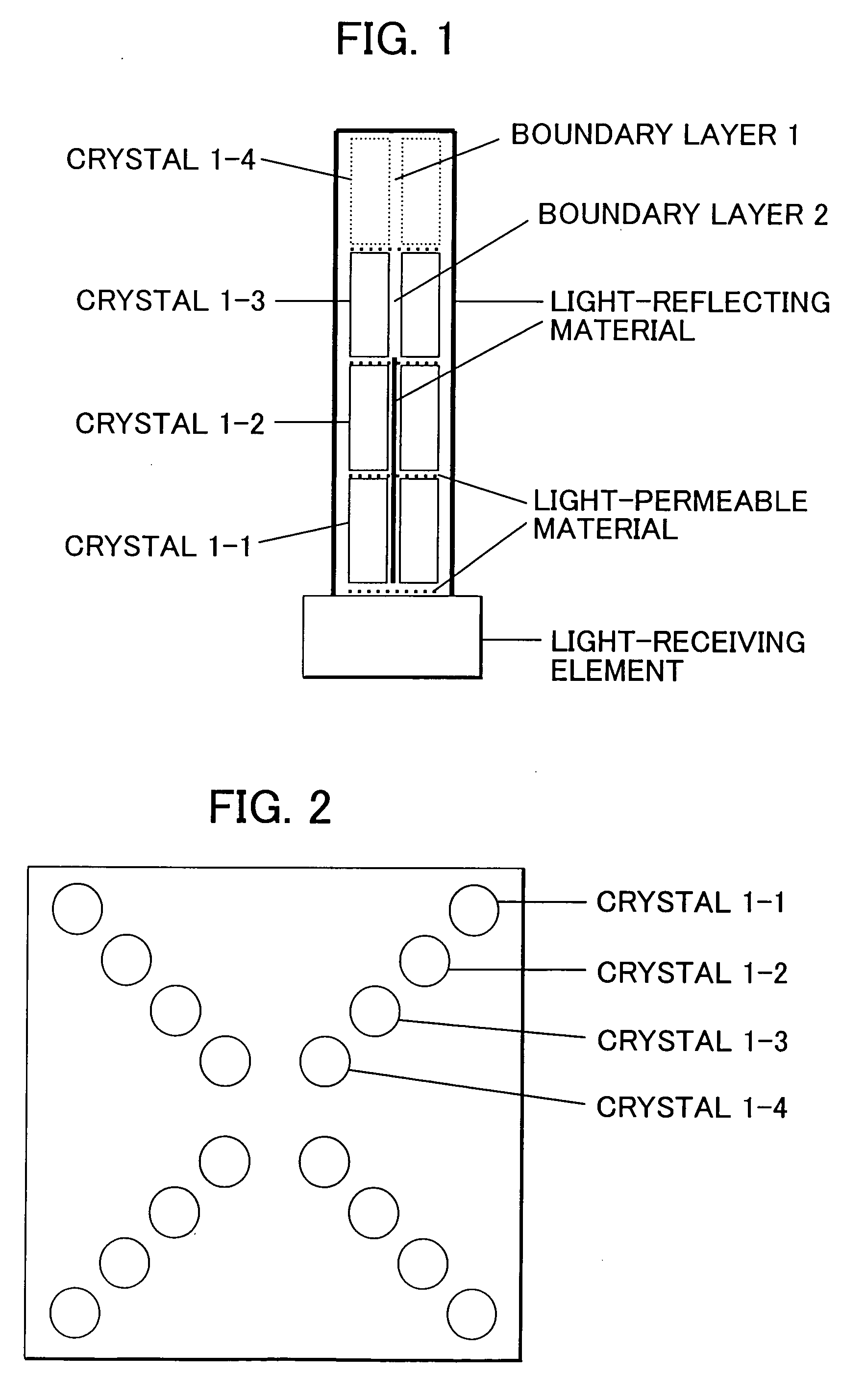
[0046]FIG. 1 is a diagram for the illustration of an embodiment of the depth of interaction detector with uniform pulse-height according to the present invention. In the depth of interaction detector with uniform pulse-height according to the present invention, scintillator cells are optically put on top of each other to form a four-layer scintillator and to thus form a scintillator unit as shown in FIG. 1. In this connection, a light-receiving element is optically coupled to each multi-layer scintillator at each end face of this scintillator unit and the external portions of the scintillator unit other than the end face are coated with a light-reflecting material (such as polytetrafluoroethylene) to a thickness (as determined after drying) of, for instance, 100 μm. Thus, the light rays generated within each scintillator cell are distributed to and arrive at these fou...


PUM


Abstract

A depth of interaction detector with uniform pulse-height comprises a multi-layer scintillator obtained by coupling at least two scintillator cells on a plane and then stacking the planar coupled scintillator cells, in layers, up to at least two stages and a light-receiving element connected to the bottom face of each scintillator cell of this multi-layer scintillator, wherein the detector is provided with a means for discriminating the position of a scintillator cell, which receives radiant rays and emits light rays and a means for making, uniform, the quantity of the light emitted from each scintillator cell and received by the light-receiving element. The detector can provide precise detection information even when radiation is absorbed by and emitted from a scintillator layer positioned above the scintillator layer optically coupled to the light-receiving element, permits the production of a depth of interaction detector having a three-dimensional depth of interaction-detecting function and can provide the same total output signal, which is independent of the position or a specific scintillator cell practically emitting light if the radiation energy is identical.

Description

BACKGROUND OF THE INVENTION [0001] The present invention relates to a depth of interaction detector with uniform pulse-height, which is a scintillation radiation detector having a function of detecting radiation depth of interaction and a function of selecting radiation absorption energy imparted thereto. [0002] Conventionally, there has been known a three-dimensional depth of interaction detector (see, for instance, Document 1 as will be given later) as a depth of interaction detector, which is a scintillation radiation detector having a function of detecting radiation depth of interaction and a function of selecting radiation absorption energy imparted thereto. In this detector, however, the conditions set for absorbed radiation energy may vary depending on every scintillation cell and they must thus be selected independently or individually. For this reason, this detector never has a structure in which radiation energies are selected through a circuit on the basis of the same sel...

Claims


Application Information

Patent Timeline
IPC IPC(8): C09K11/00G01T1/20C09K11/79G01T1/29H01L31/09
CPCG01T1/2928G01T1/2018
Inventor SUMIYA, KEIJIISHIBASHI, HIROYUKIMURAYAMA, HIDEOINADAMA, NAOKOYAMASHITA, TAKAJIOMURA, TOMOHIDE
Owner HAMAMATSU PHOTONICS KK
Learn More