Plasma display apparatus

a technology of plasma display panel and display panel, which is applied in the direction of electrical apparatus construction details, fixed connections, television systems, etc., can solve the problems of reducing the reliability of display devices, short circuit, and serious damage to both the driver ic and the plasma display panel

Inactive Publication Date: 2005-04-28
SAMSUNG SDI CO LTD
View PDF9 Cites 32 Cited by
  • Summary
  • Abstract
  • Description
  • Claims
  • Application Information

AI Technical Summary

Benefits of technology

[0017] Additionally, a high thermal conduction solid member, formed of a material selected from aluminum, copper, or iron, may be attached to the chassis base while facing the connector. In such an e

Problems solved by technology

However, as the surface of the TCP tape contacts the surface of the chassis base, rough protrusions formed on the surface of the chassis base may penetrate the solder resist layer, and contact the copp

Method used


Image

  • Plasma display apparatus
  • Plasma display apparatus
  • Plasma display apparatus

Examples


Embodiment Construction

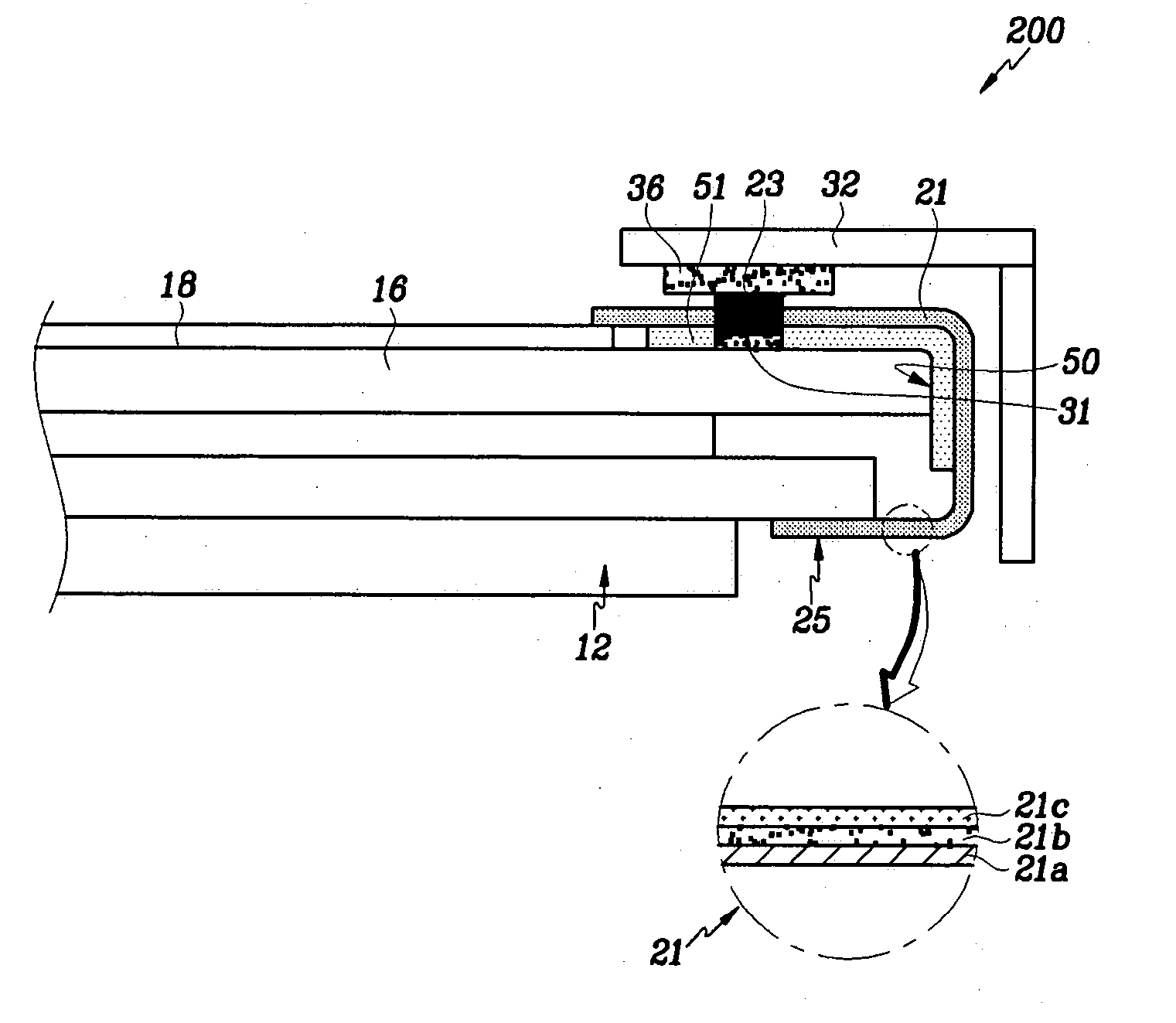
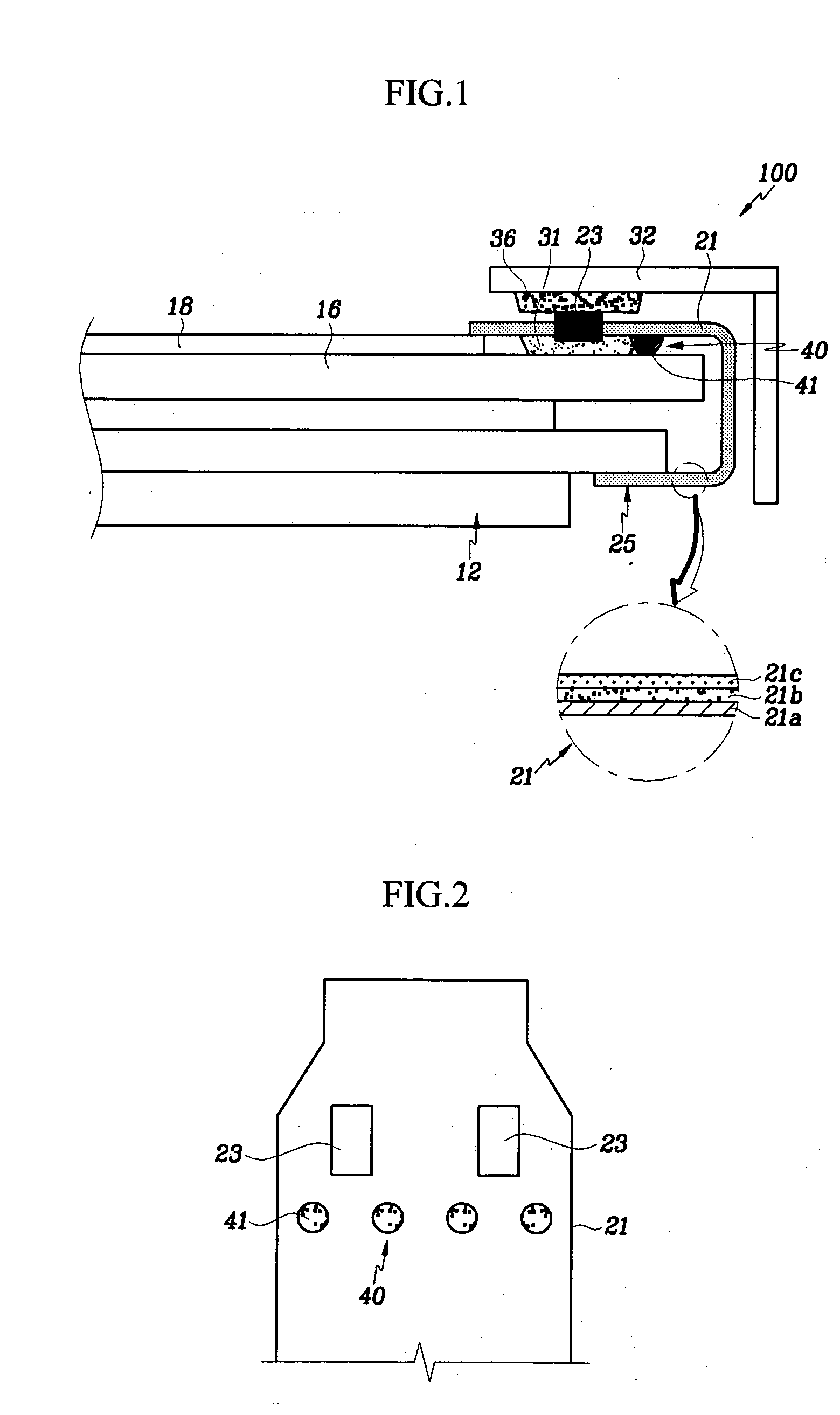
[0026] Embodiments of the invention provide an improved PDP configured to prevent electrical shorts from occurring between a driving circuit and the PDP chassis.

[0027]FIG. 1 is a sectional view of plasma display apparatus according to one embodiment of the present invention. As shown in FIG. 1, the plasma display apparatus 100 includes a plasma display panel (referred to hereinafter simply as a “PDP”) 12, and a chassis base 16. The PDP 12 is mounted on one side surface of the chassis base 16, and a driving circuit unit 18 is mounted on the opposite side surface of the chassis base 16 to drive the PDP 12. The PDP 12 has a structure where the electrodes for receiving the required signals for driving the image display are drawn from the periphery thereof. The electrodes are electrically connected to the driving circuit unit 18 via a circuit connection unit 25 to receive the signals for driving the PDP 12.

[0028] The circuit connection unit 25 is structured as a type of tape carrier pa...


PUM


Abstract

The present invention provides an improved plasma display apparatus which is configured to prevent electrical shorts in a connection between a plasma display panel (PDP and a driving circuit. In one embodiment the plasma display apparatus includes a plasma display panel, and a chassis base positioned proximate and proceeding substantially parallel the plasma display panel. The chassis base has a surface contacting the plasma display panel, and an opposite surface on which the driving circuit is mounted. A connector electrically connects the plasma display panel to the driving circuit unit. At least one spacer member is disposed between the chassis base and the connector to space the chassis base and the connector from each other with a gap.

Description

CROSS-REFERENCE TO RELATED APPLICATIONS [0001] This application claims priority of Korean Application 2003-0074230 filed in the Korean Patent Office on Oct. 23, 2003, the disclosure of which is herein incorporated by reference. BACKGROUND OF THE INVENTION [0002] 1. Field of the Invention [0003] The present invention relates to plasma display panels (PDPs) generally, and more particularly, to a structure for connecting a PDP to a circuit unit. [0004] A PDP is a display device that uses a plasma phenomenon to create and display color images. Each PDP includes millions of discharge cells. Each discharge cell is defined by barrier ribs formed between an upper substrate and a lower substrate. A dielectric layer is formed on each substrate, and crossed electrodes intersect each cell. The interior of each cell contains gas in a vacuum state, and is lined with a substrate that emits visible colored light when stimulated by ultraviolet radiation. [0005] 2. Description of Related Art [0006] S...

Claims


Application Information

Patent Timeline
IPC IPC(8): H01J17/49H01J17/16H05K7/20
CPCH05K7/20963H01R12/62H04N5/645H01J17/28H01J11/46
Inventor KIM, EUN-GONKIM, HAK-BAEKIM, KI-JUNG
Owner SAMSUNG SDI CO LTD
Why Eureka
Try Eureka