Vertically stacked turnstile array

Inactive Publication Date: 2005-04-28
THALES NORTH AMERICA
View PDF0 Cites 17 Cited by
  • Summary
  • Abstract
  • Description
  • Claims
  • Application Information

AI Technical Summary

Benefits of technology

[0016] The present invention includes an antenna array for mitigating multi-path based on angle-of-arrival differences. It also includes a signal processor to process signal processing algorithms to combine the output of the array elements to minimize the effect of interferences and multi-path.
[0017] The combining technique explicitly takes into account variation or uncertainty in the assumed array response. Sources of this uncertainty include imprecise knowledge of the angle of arrival and uncertainty in the array manifold. In one example embodiment of the present invention, uncertainty in the array manifold is modeled explicitly via an uncertainty ellipsoid that gives the possible values of the array for a particular look direction. Weights are chosen to minimize the total weighted power output of the array, subject to the constraint that the gain exceeds unity for all array responses in this uncertainty ellipsoid. Hence, the present inv

Problems solved by technology

Sources of this uncertainty include imprecise knowledge of

Method used


Image

  • Vertically stacked turnstile array
  • Vertically stacked turnstile array
  • Vertically stacked turnstile array

Examples


Example

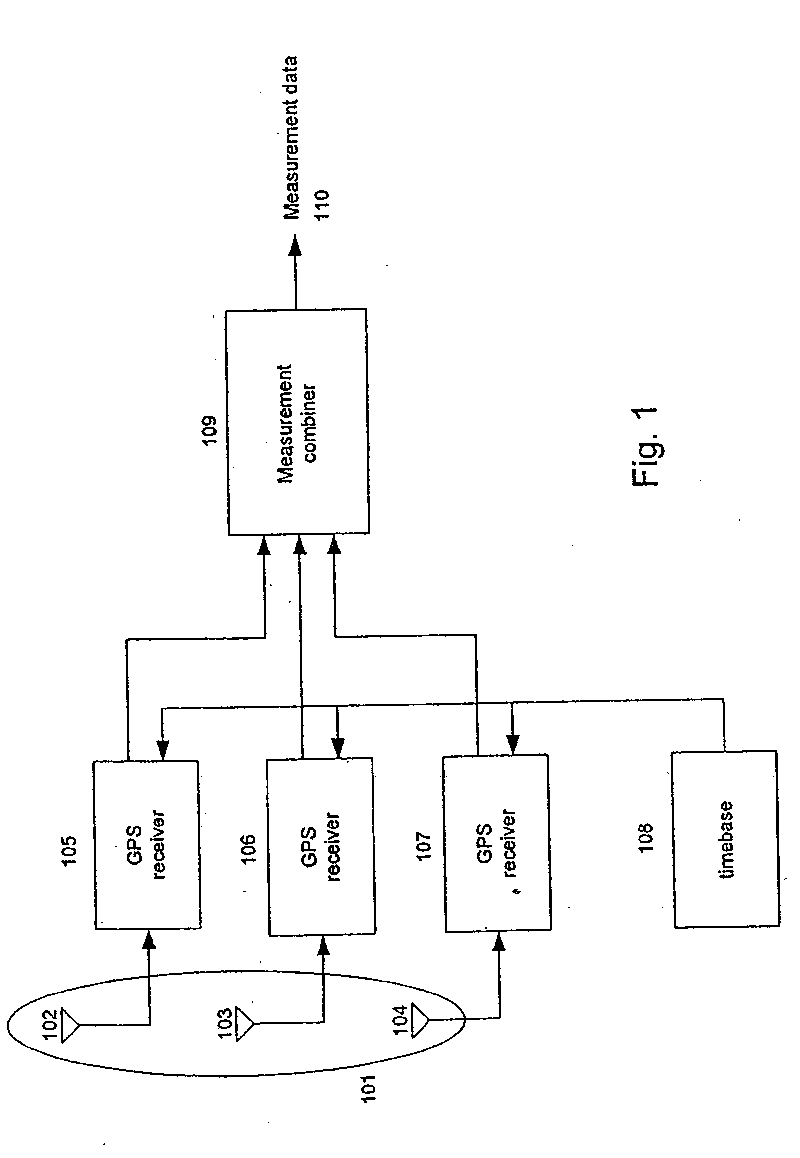
[0027] Referring to FIG. 1, the system embodying the present invention is shown. Signals are received at an antenna array 101 consisting of a plurality of antenna elements 102, 103, and 104. The outputs of antenna elements 102, 103, and 104 are respectively connected to a plurality of receivers (such as GPS receivers) 105-107. The GPS receivers 105-107 are additionally connected to a common timebase 108. The stability of the timebase 108 is not critical. For example, the timebase 108 may comprise a temperature compensated crystal oscillator.

[0028] Antenna elements 102, 103, and 104 of array 101 are, for example, identical turnstile elements arranged in a vertical collinear fashion. The turnstile antennas 102, 103, and 104 are optimally spaced apart at approximately a ½ of a wavelength at the highest frequency of use. A spacing of greater than a half of a wavelength creates ambiguity in the received number of carrier cycles. Closer spacing reduces the effectiveness of the antenna an...


PUM


Abstract

A system includes an antenna array consisting of a plurality of antenna elements, a plurality of receivers to process the signals from the antenna elements of the antenna array, and a combiner to combine receiver outputs so as to minimize the effect of undesirable signals such as multipath or interference while maintaining a nominal gain in the direction of the desired signal. The combiner takes into account variation or uncertainty in the assumed antenna array response, such as imprecise knowledge of the angle of arrival and uncertainty in the array manifold and multiplicative uncertainties due to gain variations between receivers, as well as non-uniformity in the response due to coupling between elements and coupling with the antenna structure. This system is applicable to antenna arrays with non-uniform responses, such as closely spaced arrays in which the coupling between elements is significant.

Description

CROSS-REFERENCE TO RELATED APPLICATIONS AND CLAIM OF PRIORITY [0001] The present invention is a continuation of Provisional Application Nos. 60 / 326,522 and 60 / 352,716, respectively filed in the U.S. Patent and Trademark Office on Oct. 1, 2001 and Jan. 28, 2002 and priority is hereby claimed under 35 USC 119 with respect to these two provisional applications.APPENDIX [0002] The attached appendix contains an article entitled: “Robust Beamforming in GPS Arrays” by Robert G. Lorenz and Stephen P. Boyd, ION National Technical Meeting, Jan. 28-30, 2002, San Diego, Calif. The contents of this article, omitted from the Detailed Description below for the sake of brevity, include very detailed analyses of some of the features of the present invention and are incorporated by reference herein in its entirety. BACKGROUND OF THE INVENTION [0003] 1. Field of the Invention [0004] The present invention relates to processing signals, such as GPS signals, received by a plurality of antenna elements fo...

Claims


Application Information

Patent Timeline
IPC IPC(8): G01S19/25H04B7/08
CPCH04B7/0808H04B7/0874H04B7/0854H04B7/0822
Inventor LORENZ, ROBERT G.
Owner THALES NORTH AMERICA
Why Eureka
Try Eureka