Drainage management systems and methods

Inactive Publication Date: 2005-04-28
AMEC GEOMATRIX
View PDF9 Cites 6 Cited by
  • Summary
  • Abstract
  • Description
  • Claims
  • Application Information

AI Technical Summary

Benefits of technology

[0006] The present invention is directed to a flow limiting inlet structure designed to collect water or other fluids in a pool above grade, and to provide improved capture of sediments and surface pollutants such as oils and greases in the pool, while regulating the flow of water or other fluids during discharge into an outlet pipe. More particularly, the present invention is directed to

Problems solved by technology

The flushing of pollutants into such drainage systems is generally undesirable, particularly if the water or other fluids flowing through such drainage systems remain untreated before being discharged into a river, lake, or ocean.
First flush events are particularly troublesome in industrial areas due to the types and amounts of pollutants that accumulate.
Because the effects of first flush events are undesirable, efforts have been made to limit such effects.
A concern in designing such flow limiting structures is that they should not allow flooding to occur, even if preventing floodi

Method used


Image

  • Drainage management systems and methods
  • Drainage management systems and methods
  • Drainage management systems and methods

Examples


Example

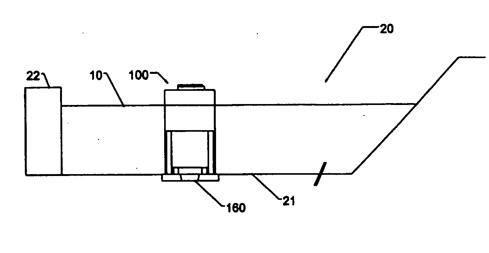
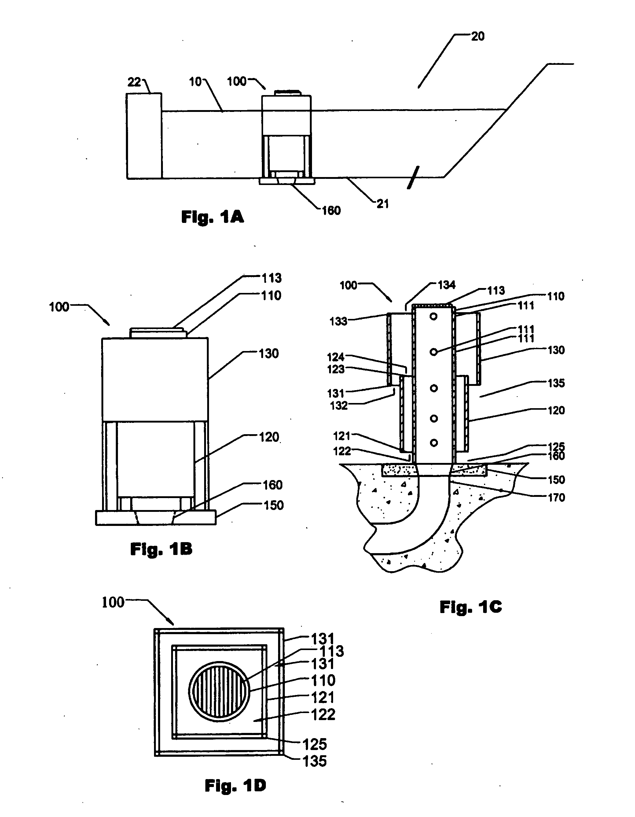
[0029] In FIG. 1A, a flow limiting structure 100 is positioned in a detention basin 20 where basin 20 is partially bounded by basin bottom 21 and by basin perimeter weir 22, and basin 20 includes an outlet 160. Basin 20 contains sediment and surface pollutant containing water 10, and structure 100 controls the flow of water 10 (or any other fluid in basin 20) out of basin 20 through outlet 160. In preferred embodiments, weir 22 is adapted to spill water out of basin 20 when water 10 reaches a height sufficient to overflow structure 100.

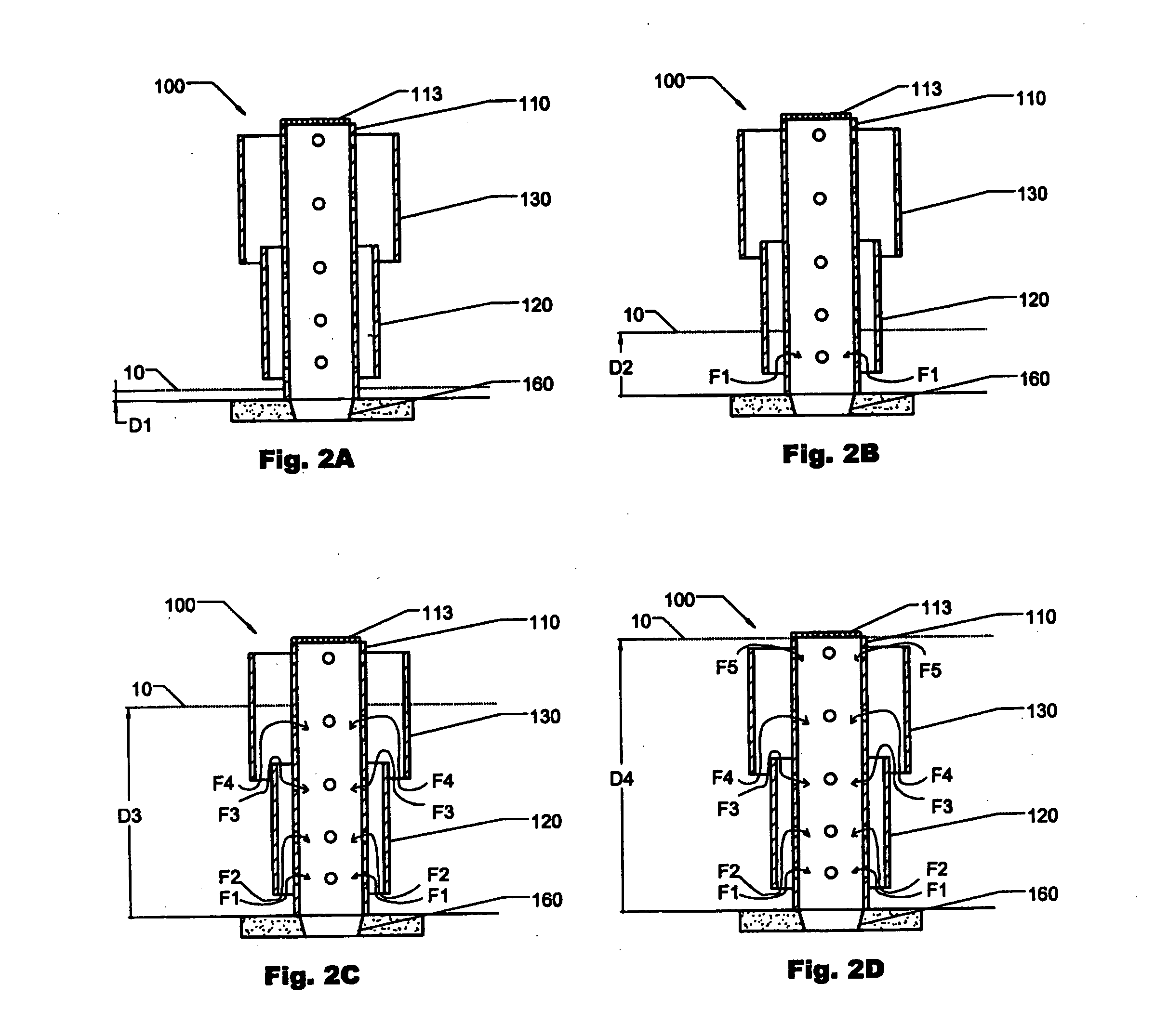
[0030] As can be seen in FIGS. 1A-1D, flow limiting structure 100 comprises a perforated riser 110 having holes 111 and opening 112 covered by hinged grate 113, and a set of two nested and tiered baffles 120 and 130, each baffle (120, 130) comprising lower edges (121, 131) forming lower openings (122, 132), upper edges (123, 133) forming upper openings (124, 134), and a set of support legs (125, 135), separating lower edges (121, 131), from a foundat...


PUM

PropertyMeasurementUnit
Flow rateaaaaaaaaaa
Structureaaaaaaaaaa
Areaaaaaaaaaaa

Abstract

A flow limiting inlet structure is designed to collect water or other fluids in a pool above grade, and to provide improved capture of sediments and surface pollutants such as oils and greases in the pool, while regulating the flow of water or other fluids during discharge into an outlet pipe. In a conventional storm water detention basin a vertical cylindrical discharge structure can be used to regulate the basin water depth and discharge flow rate of storm water out of the detention basin, in conjunction with the use of a specially designed baffle system that prevents the release of any greases or oils floating on the water surface while capturing any floating trash or debris.

Description

FIELD OF THE INVENTION [0001] The field of the invention is drainage management systems, more particularly, flow limiting inlet structures designed to collect water or other fluids in a pool above grade and to regulate water discharge, enabling the system to capture sediments and surface pollutants such as oil and grease in the pool before allowing the collected water to discharge into an outlet pipe. BACKGROUND OF THE INVENTION [0002] Contaminated sediments, greases, and oils, and other pollutants collect on the ground during dry periods when little or no rainfall occurs. When a storm occurs after such a dry period, the accumulated pollutants are mobilized by storm water and get flushed into surface water drainage systems. The flushing of pollutants into such drainage systems is generally undesirable, particularly if the water or other fluids flowing through such drainage systems remain untreated before being discharged into a river, lake, or ocean. The occurrence of a storm after ...

Claims


Application Information

Patent Timeline
IPC IPC(8): B01D17/02E03F5/10
CPCE03F5/106B01D17/0214
Inventor SIMPSON, TIMOTHY S.COPPOLA, GREGORYBORREGO, RON
Owner AMEC GEOMATRIX
Why Eureka
Try Eureka