Rotating fluid machine

Inactive Publication Date: 2005-04-28
HONDA MOTOR CO LTD
View PDF0 Cites 5 Cited by
  • Summary
  • Abstract
  • Description
  • Claims
  • Application Information

AI Technical Summary

Benefits of technology

[0009] With the configuration described above, as the arrangement of the annular first sealing member on the outer circumference of the mating faces of the valve body and the stationary valve plate of the rotary valve of the rotating fluid machine encloses both the high pressure working medium passages and the low pressure working medium passages penetrating the mating faces inside in their radial direction, the pressure of a high pressure working medium leaking out of the high pressure working medium passages to the mating faces is caused to act on substantially the whole area of the mating faces, thereby preventing local deformation of the stationary valve plate and ensuring close contact between the sliding faces. Also, since the annular second sealing member is arranged around the low pressure working medium passages inside the first sealing member in the radial direction, the second sealing member prevents the high pressure working medium on the mating faces from being discharged to the low pressure working medium passages. As the second sealing member encloses only a narrow area around the low pressure working medium passages, there is no fear that low pressure locally deforms the stationary valve plate.
[0011] With the configuration described above, as the opening of the first sealing member comprising a C-shaped seal is arranged inward in the radial direction, the sealing performance of the first sealing member can be increased by the pressure of a high pressure working medium leaking from the high pressure working medium passages to the mating faces, thereby preventing the high pressure working medium from being discharged outside from the mating faces. Further, as the opening of the second sealing member comprising a C-shaped seal is arranged outward in the radial direction, the sealing performance of the second sealing member can be increased by the pressure of a high pressure working medium leaking to the mating faces, thereby preventing the high pressure working medium from being discharged out of the mating faces to the low pressure working medium passages.

Problems solved by technology

Therefore, there is a possibility that the high pressure and the low pressure act locally on the stationary valve plate to invite flexural deformation, whereby the close contact between its sliding face and that of the moving valve plate is lost, so that high temperature high pressure steam leaks.

Method used


Image

  • Rotating fluid machine
  • Rotating fluid machine
  • Rotating fluid machine

Examples


Embodiment Construction

[0029] A preferred embodiment of the present invention will be described below with reference to the accompanying drawings.

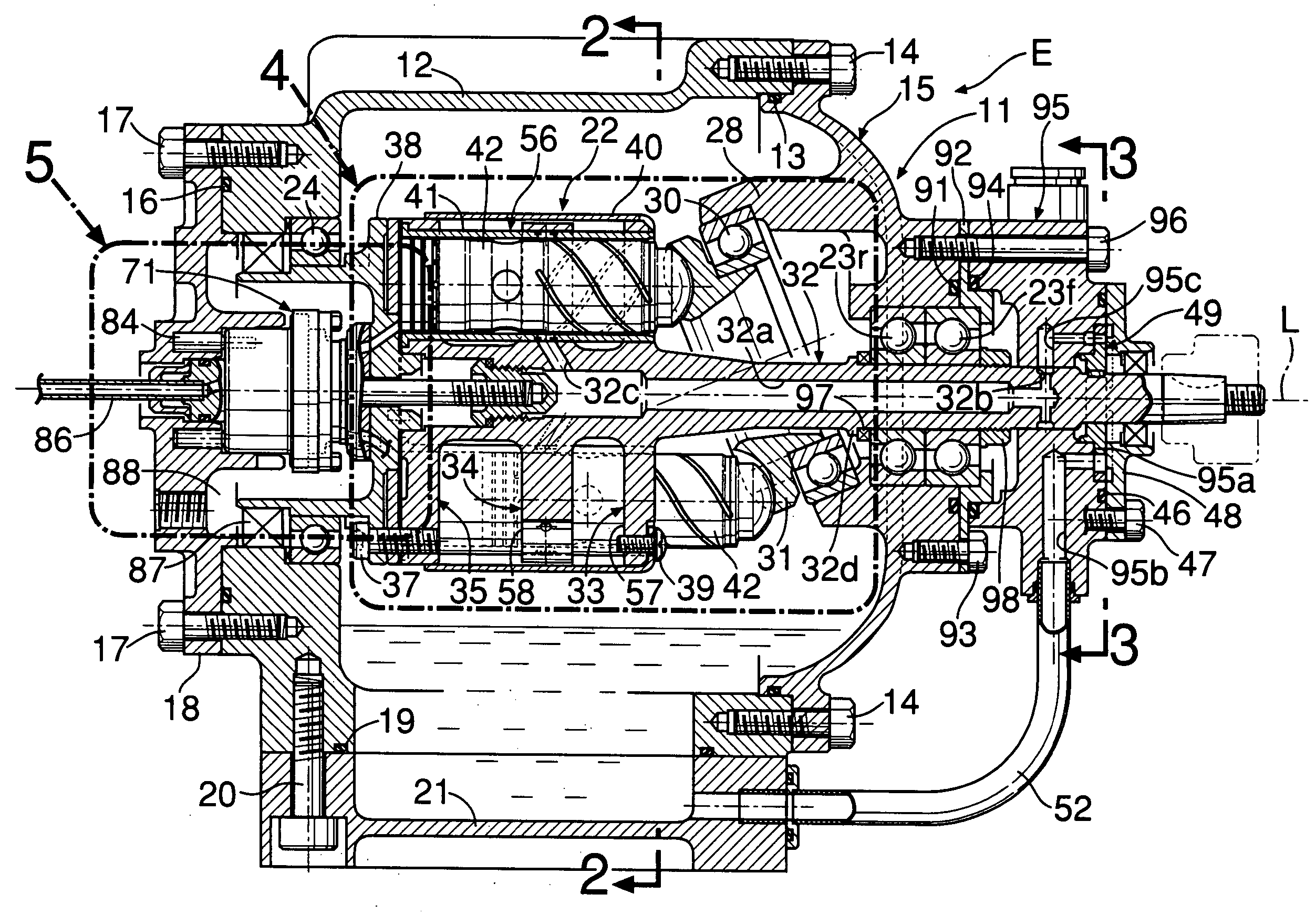
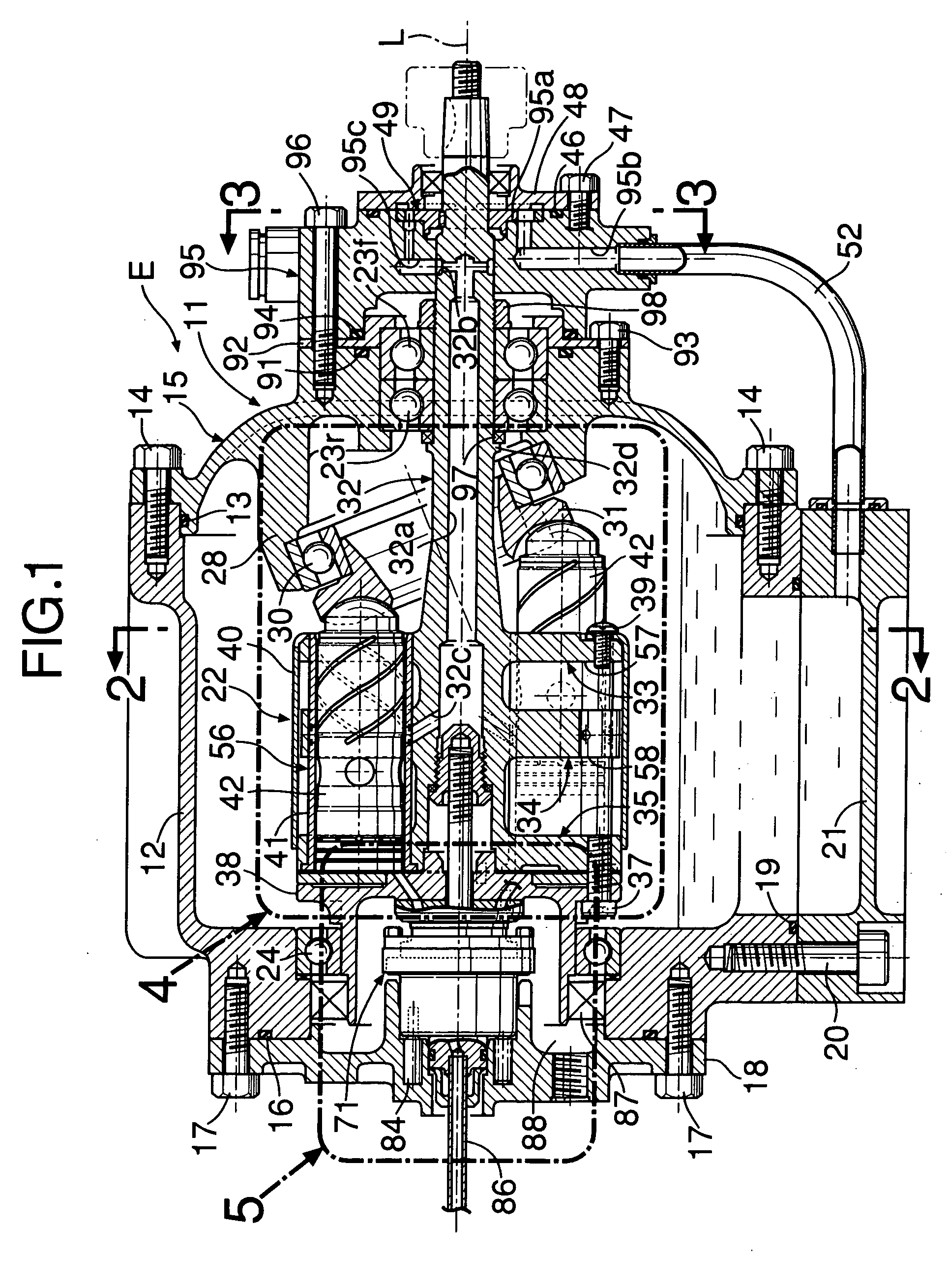
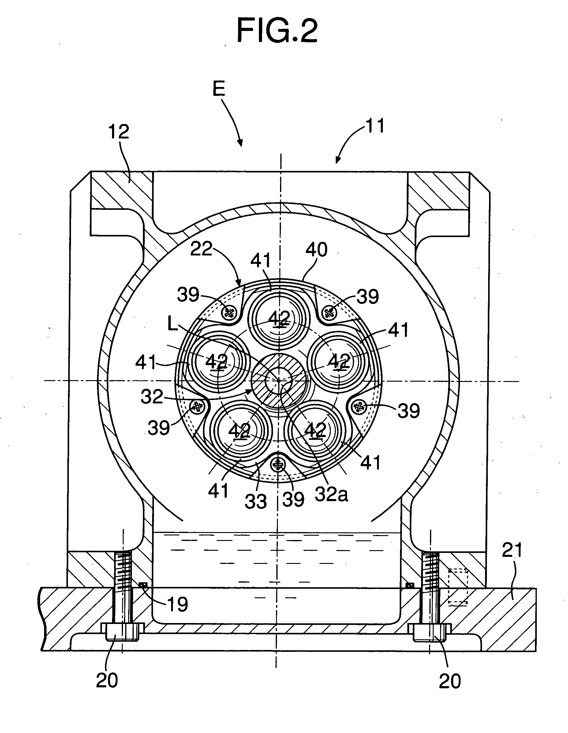
[0030] As shown in FIG. 1 through FIG. 9, an expander E according to an embodiment is used in, for example, a Rankine cycle system. It converts thermal energy and pressure energy of high-temperature high-pressure steam as a working medium into mechanical energy and supplies the converted energy. The casing 11 of the expander E is provided with a casing body 12, a front cover 15 connected to the front opening of the casing body 12 with a plurality of bolts 14 . . . with a sealing member 13 therebetween, a rear cover 18 fitted to the rear opening of the casing body 12 with a plurality of bolts 17 . . . with a sealing member 16 therebetween, and an oil pan 21 fitted to the bottom opening of the casing body 12 with a plurality of bolts 20 . . . with a sealing member 19 therebetween.

[0031] A rotor 22 is arranged to be rotatable around an axis L extending in the mid...


PUM


Abstract

A rotary valve of a rotating fluid machine is constructed by bringing, into contact on sliding faces, a moving valve plate and a stationary valve plate, and high pressure working medium passages and low pressure working medium passages penetrate mating faces of a valve body and the stationary valve plate. By sealing the outer circumference of the mating faces with a first sealing member and sealing the circumference of the low pressure working medium passages with a second sealing member inside the first sealing member in the radial direction, the pressure of a high pressure working medium leaking out of the high pressure working medium passages to the mating faces is caused to act on substantially the whole area of the mating faces, thereby preventing local deformation of the stationary valve plate and ensuring close contact between the sliding faces.

Description

BACKGROUND OF THE INVENTION [0001] 1. Field of the Invention [0002] The present invention relates to a rotating fluid machine provided with a casing, a rotor rotatably supported by the casing, a working section provided on the rotor, and a rotary valve, provided between the casing and the rotor, for controlling the supply and discharge of the working medium to and from the working section. [0003] 2. Description of the Related Art [0004] In a rotary valve for rotating fluid machines of this kind, a moving valve plate provided on the rotor and a stationary valve plate provided on a valve body engaged with the casing to be unable to rotate and movable in the direction of the axis of the rotor are brought into contact with each other on sliding faces orthogonal to the axis, and the rotation of the moving valve plate relative to the stationary valve plate causes steam of high temperature and high pressure to be successively supplied to or discharged from a group of axial piston cylinders...

Claims


Application Information

Patent Timeline
IPC IPC(8): F01B3/02F03C1/34F04B1/20
CPCF01B3/02F04B1/2042F04B1/2014F03C1/0655
Inventor MATSUMOTO, KENJIITOH, NAOKI
Owner HONDA MOTOR CO LTD
Why Eureka
Try Eureka