Planetary-gear-type multiple-step transmission for vehicle

a transmission device and planetary gear technology, applied in the direction of mechanical equipment, transportation and packaging, gearing, etc., can solve the problems of increasing the overall length of the transmission, difficult to fully satisfy the requirements, poor maneuverability of the transmission, etc., to simplify the control of the frictional coupling device and the effect of simple construction

Inactive Publication Date: 2005-04-28
TOYOTA JIDOSHA KK
View PDF6 Cites 194 Cited by
  • Summary
  • Abstract
  • Description
  • Claims
  • Application Information

AI Technical Summary

Benefits of technology

[0023] Each of the above-described first through fifteenth aspects of the invention provides the planetary-gear-type multiple-step transmission which is capable of establishing the drive positions with relatively width range of speed ratio and appropriate ratio steps between adjacent drive positions, by selectively engaging and releasing the four clutches and the two brakes. Further, the transmission of the invention can be made compact in size owing to its simple construction in which the first transmission unit is constituted principally by the two intermediate transmitting paths having the respective different speed ratios while the second transmission unit is constituted principally by the two planetary gear sets.
[0024] In the planetary-gear-type multiple-step transmission constructed according to the above-described third, fourth, eighth or

Problems solved by technology

However, these requirements are difficult to be fully satisfied.
In the multiple-step transmission disclosed in JP-2002-206601A, the speed ratios of the respective drive positions do not change in geometric progression, thereby resulting in a poor maneuverability in the transmission.
However, the increa

Method used


Image

  • Planetary-gear-type multiple-step transmission for vehicle
  • Planetary-gear-type multiple-step transmission for vehicle
  • Planetary-gear-type multiple-step transmission for vehicle

Examples


first embodiment

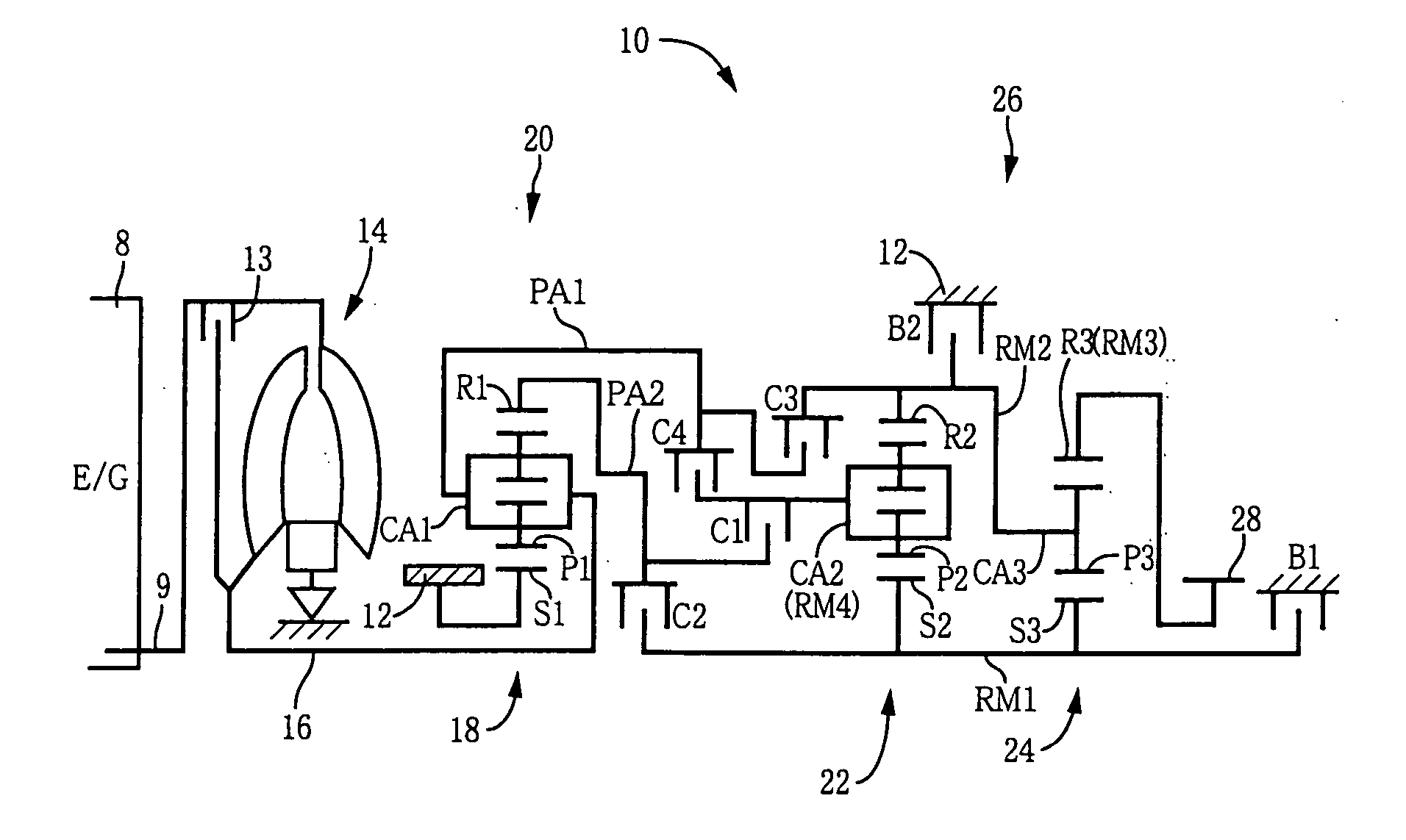
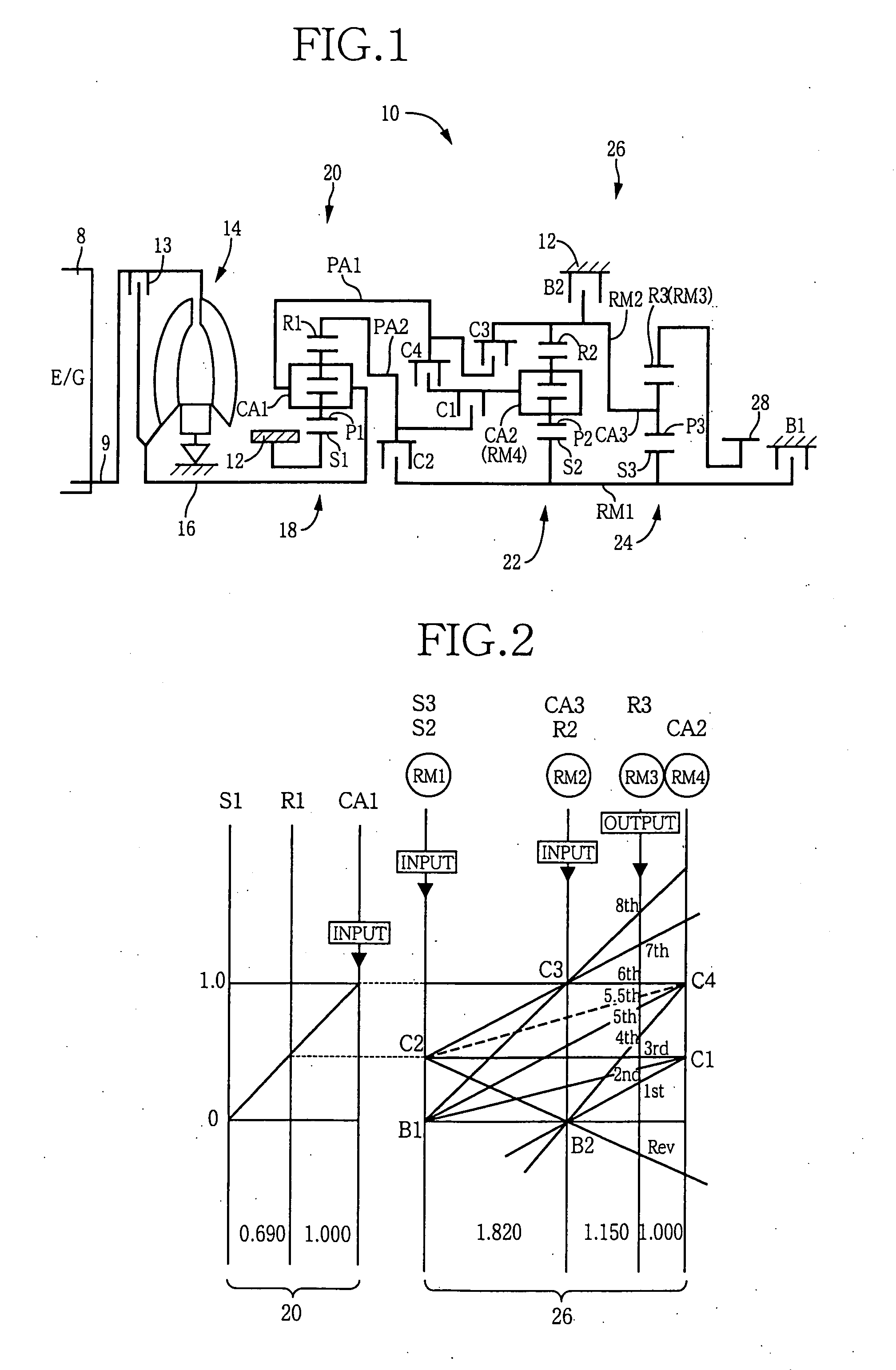
[0043] Referring to first to the schematic view of FIG. 1, there is illustrated a basic arrangement of a vehicle automatic transmission in the form of a vehicle planetary gear type multiple-step transmission (hereinafter referred to simply as “transmission”) 10, which is to be disposed between an engine 8 as a drive power source and drive wheels (not shown) so as to transmit an output of the engine 8 to the drive wheels. As shown in FIG. 1, the transmission 10 has a transmission casing 12 to be fixed to the body of the vehicle, and includes: a hydraulic transmission unit in the form of a torque converter 14 equipped with a lock-up clutch 13; an input shaft 16 connected to the torque converter 14; a first transmission unit 20 constituted principally by a first planetary gear set 18; a second transmission unit 26 constituted principally by a second planetary gear set 22 and a third planetary gear set 24; and an output gear 28. The torque converter 14, the input shaft 16, the first tra...

second embodiment

[0069] In this second embodiment, the first rotary module RM1 is constituted by the carrier CA2 of the second planetary gear set 64 and the sun gear S3 of the third planetary gear set 24 which are connected to each other. The second rotary module RM2 is constituted by the ring gear R2 of the second planetary gear set 64 and the carrier CA3 of the third planetary gear set 24 which are connected to each other. The third rotary module RM3 is constituted by the ring gear R3 of the third planetary gear set 24. The. fourth rotary module RM4 is constituted by the sun gear S2 of the second planetary gear set 64.

[0070] The connection of each of the first through fourth rotary modules RM1-RM4 with the transmission casing 12, the intermediate transmitting paths PA1, PA2 or the output gear 28 in this second embodiment is the same as that in the above-described first embodiment. Described specifically, the first rotary module RM1 (CA2, S3) is selectively connected to the transmission casing 12 t...

third embodiment

[0074] In this third embodiment, the first rotary module RM1 is constituted by the sun gear S2 of the second planetary gear set 22 and the sun gear S3 of the third planetary gear set 74 which are connected to each other. The second rotary module RM2 is constituted by the ring gear R2 of the second planetary gear set 22. The third rotary module RM3 is constituted by the carrier CA3 of the third planetary gear set 74. The fourth rotary module RM4 is constituted by the carrier CA2 of the second planetary gear set 22 and the ring gear R3 of the third planetary gear set 74 which are connected to each other.

[0075] The connection of each of the first through fourth rotary modules RM1-RM4 with the transmission casing 12, the intermediate transmitting paths PA1, PA2 or the output gear 28 in this third embodiment is the same as that in the above-described first embodiment. Described specifically, the first rotary module RM1 (S2, S3) is selectively connected to the transmission casing 12 throu...


PUM


Abstract

A planetary-gear-type multiple-step transmission including a stationary member, an input rotary member, an output rotary member, and first and second transmission units. The first transmission unit has first and second intermediate transmitting paths through which a rotary motion of the input rotary member is transmittable to the second transmission unit such that a speed of the rotary motion transmitted through the second intermediate transmitting path is lower than a speed of the rotary motion transmitted through the first intermediate transmitting path. The second transmission unit constitutes first, second, third and fourth rotary modules, each of which is provided by at least one of sun gears, carriers and ring gears of two planetary gear sets. The first rotary module is selectively connected to the second intermediate transmitting path, while being selectively connected to the stationary member. The second rotary module is selectively connected to the first intermediate transmitting path, while being selectively connected to the stationary member. The third rotary module is connected to the output rotary member. The fourth rotary module is selectively connected to the first intermediate transmitting path, while being selectively connected to the second intermediate transmitting path.

Description

[0001] This application is based on Japanese Patent Application No. 2003-365691 filed in Oct. 27, 2003, the content of which is incorporated hereinto by reference. BACKGROUND OF THE INVENTION [0002] 1. Field of the Invention [0003] The present invention relates to a planetary-gear-type multiple-step transmission interposed between a drive power source and drive wheels of a vehicle such as an automobile. [0004] 2. Discussion of Related Art [0005] For vehicle, there is widely used a planetary-gear-type multiple-step transmission which is equipped with a plurality of planetary gear sets, as disclosed in JP-2002-206601A. In such a planetary-gear-type multiple-step transmission, a plurality of predetermined speed ratios or drive positions (gear positions) are selectively established by connecting elements of the planetary gear sets through coupling devices such as clutches and brakes. For example, in the transmission disclosed in JP-2002-206601A, a total of twelve forward drive positions...

Claims


Application Information

Patent Timeline
IPC IPC(8): F16H3/62F16H3/66
CPCF16H3/666F16H2200/006F16H2200/2097F16H2200/201F16H2200/2046F16H2200/0065
Inventor ABE, AKIHARUHOSHINO, AKIRATABATA, ATSUSHIHONDA, ATSUSHIMIYAZAKI, TERUFUMIOTA, HIROFUMI
Owner TOYOTA JIDOSHA KK
Why Eureka
Try Eureka