

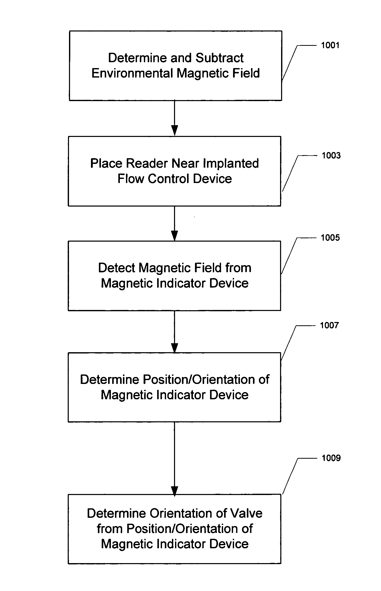
Electronic valve reader
a technology of electronic valves and indicators, applied in the field of medical devices, can solve the problems of incorrect device setting indications, interference with the compass, inaccurate setting indications provided by a compass-based indicator tool, etc., and achieve the effect of reducing the effect of an external magnetic field, enhancing the accuracy of the tool, and more accurate and reliable indications of implantable device settings
- Summary
- Abstract
- Description
- Claims
- Application Information
AI Technical Summary
Benefits of technology
Problems solved by technology
Method used
Image

Examples
Embodiment Construction
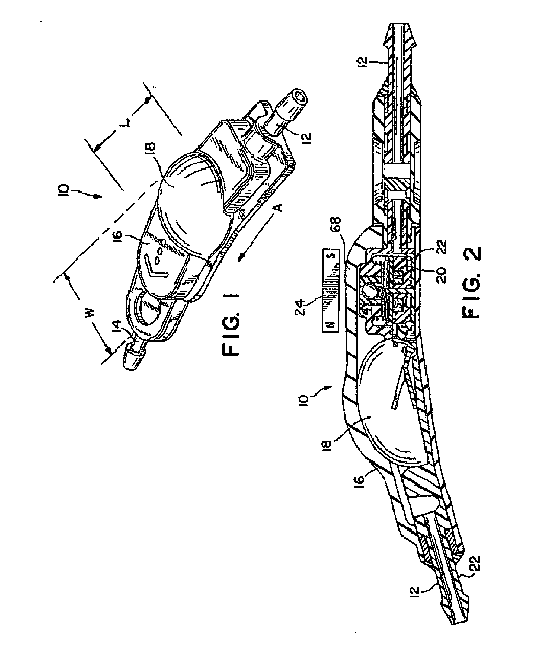
[0026] As shown in the drawings for purposes of illustration, the FIGS. 1 and 2 illustrate a subcutaneously implantable and percutaneously adjustable fluid flow control device, generally designated in the accompanying drawings by the reference numbers 10. The fluid flow control devices 10 is intended for use in a surgically implanted physiological shunt system for draining fluid from one portion of the body to another. In order to connect, for example, the device 10 in such a system, the device includes an inlet connector 12 and an outlet connector 14 which each receive one end of a piece of surgical tubing (not shown). The ends of the surgical tubing are placed over the connectors 12 and 14 and secured thereon by a single ligature just inside of an annular ridge formed near the end of each connector.
[0027] When the flow control device 10 is used in a drainage system intended for the treatment of hydrocephalus, the inlet connector 12 is fluidly connected with a proximal catheter th...
PUM
 Abstract
Description
Claims
Application Information