Vibration damper systems for drilling with casing

a casing and vibration damper technology, which is applied in the direction of drilling rods, drilling pipes, drilling holes/well accessories, etc., can solve the problems of increasing operational time and costs, time-consuming and expensive traditional method of drilling with drill strings (pipes with drill bits on the bottom) to form wellbores, and drilling with casings is sometimes more prone to drilling vibrations than conventional drilling pipe strings. , to achieve the effect of reducing drilling vibration and reducing the vibration of rotating cas

Active Publication Date: 2005-05-05
WEATHERFORD TECH HLDG LLC
View PDF24 Cites 27 Cited by
  • Summary
  • Abstract
  • Description
  • Claims
  • Application Information

AI Technical Summary

Benefits of technology

[0013] Embodiments of the present invention generally provide apparatus and methods for reducing drilling vibration during drilling with casing. In one embodiment, an apparatus for reducing vibration of a rotating casing includes a tubular body disposed concentrically around the casing, wherein tubular body is movable relative to the casing. Preferably, a portion of the tubular body comprises a friction reducing material. In operation, the tubular body comes into contact with the existing casing or the wellbore instead of the rotating casing. Because the tubular body is freely movable relative to the rotating casing, the rotating casing may continuously rotate even though the tubular body is frictionally in contact with the existing casing.
[0019] In another embodiment still, a method for reducing vibration of a rotating casing includes disposing a tubular body around the casing such that the tubular body is movable relative to the casing. During operation the tubular body frictionally engages the surrounding wall instead of the casing, thereby permitting the casing to rotate continuously.

Problems solved by technology

Because of the two run-in requirement, the traditional method of using the drillstring (pipe with drill bit on bottom) to form a wellbore is time consuming and expensive.
The time required to remove the drilling string as the wellbore is extended results in an increase of operational time and costs.
While drilling with casing provides an efficient system for wellbore completion, the system does have its drawbacks.
For example, drilling with casing is sometimes more prone to drilling vibrations than the conventional drill pipe string.
Excessive drilling vibration is a cause of premature failure or wear of drilling components and drilling inefficiency.
Backwards whirl occurs due to lateral vibrations caused by the drillstring eccentricity, which may lead to centripetal forces during rotation.
The end result is an increase in drilling vibration and torque, sometimes to unacceptable levels.

Method used


Image

  • Vibration damper systems for drilling with casing
  • Vibration damper systems for drilling with casing
  • Vibration damper systems for drilling with casing

Examples


Embodiment Construction

[0037] Methods and apparatus are provided for reducing the occurrence of drilling vibration when performing drilling with casing.

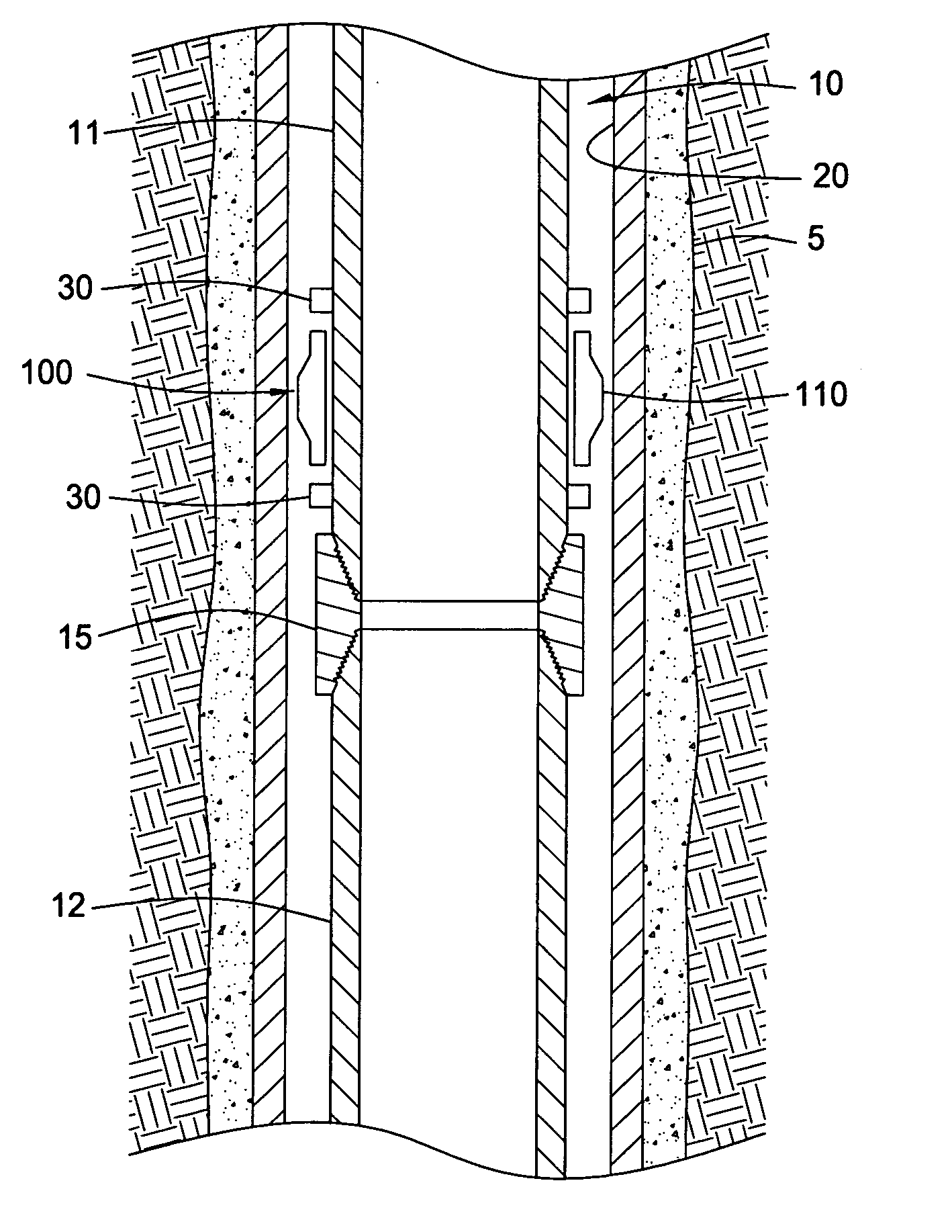
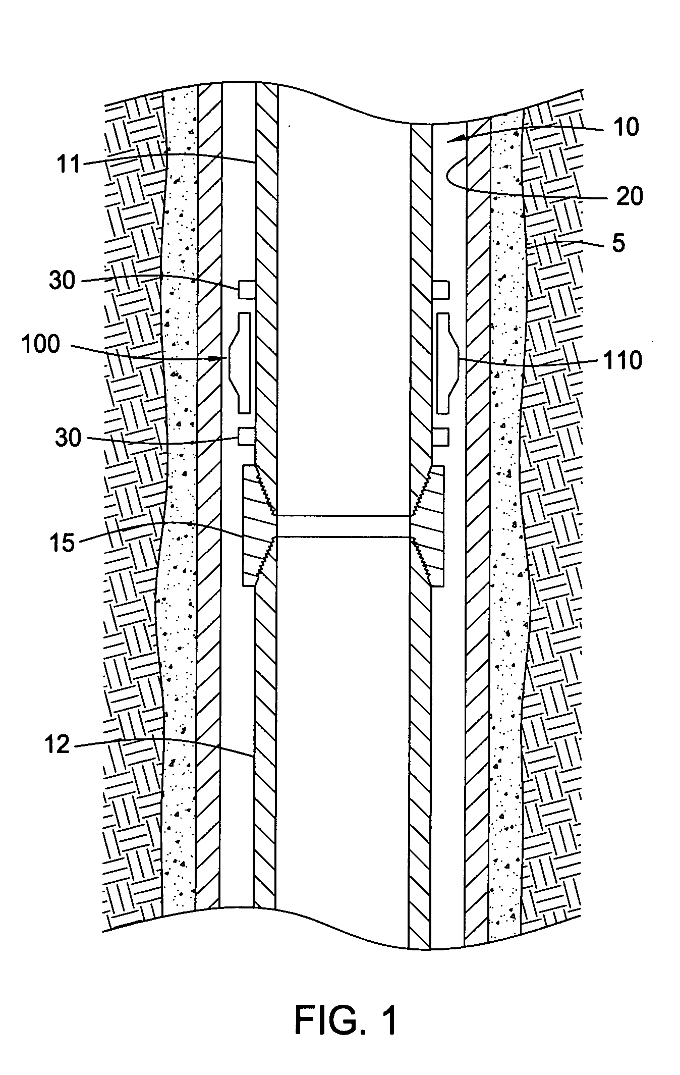
[0038]FIG. 1 shows partial view of a drilling casing 10 disposed in an existing casing 20. The existing casing 20 has been cemented to line the wellbore 5. The drilling casing 10 is run into the wellbore 5 with a drilling assembly disposed at a lower portion to extend the wellbore 5. The drilling casing 10 is shown with two casing sections 11, 12 connected together by a coupling 15. Moreover, the coupling 15 has a larger outer diameter than the casing sections 11, 12. Therefore, the coupling 15 is more likely to contact the existing casing 20 than the casing sections 11, 12 during rotation.

[0039] In FIG. 1, the drilling casing 10 is equipped with a friction reducing tool 100 for minimizing drilling vibration. In one aspect, the friction reducing tool 100 is positioned on the drilling casing 10 between two stop collars 30. The collars 30 limit the axial m...


PUM

PropertyMeasurementUnit
frictionaaaaaaaaaa
axial movementaaaaaaaaaa
hardnessaaaaaaaaaa

Abstract

Apparatus and methods are provided for reducing drilling vibration during drilling with casing. In one embodiment, an apparatus for reducing vibration of a rotating casing includes a tubular body disposed concentrically around the casing, wherein tubular body is movable relative to the casing. Preferably, a portion of the tubular body comprises a friction reducing material. In operation, the tubular body comes into contact with the existing casing or the wellbore instead of the rotating casing. Because the tubular body is freely movable relative to the rotating casing, the rotating casing may continuously rotate even though the tubular body is frictionally in contact with the existing casing.

Description

CROSS-REFERENCE TO RELATED APPLICATIONS [0001] This application claims benefit of co-pending U.S. Provisional Patent Application Ser. No. 60 / 515,391, filed on Oct. 29, 2003, which application is herein incorporated by reference in its entirety.BACKGROUND OF THE INVENTION [0002] 1. Field of the Invention [0003] Embodiments of the present invention generally relate to methods and apparatus for drilling with casing. Particularly, the present invention relates to methods and apparatus for reducing drilling vibration while drilling with casing. Additionally, the present invention relates to apparatus and methods for manufacturing a vibration damper. [0004] 2. Description of the Related Art [0005] In the drilling of oil and gas wells, a wellbore is formed in a formation using a drill bit that is urged downwardly at a lower end of a drill string. To drill within the wellbore to a target depth, the drill string is often rotated by a top drive or rotary table on a surface platform or rig, or...

Claims


Application Information

Patent Timeline
Patent Type & Authority Applications(United States)
IPC IPC(8): E21B17/10
CPCE21B17/1007Y10T29/49805E21B17/1064
Inventor LE, TUONG THANHGIROUX, RICHARD L.ODELL, ALBERT C.THOMPSON, GARYBANTA, DEBORAH L.BADRAK, ROBERT P.GALLOWAY, GREGORY G.FULLER, MARK S.
Owner WEATHERFORD TECH HLDG LLC
Why Eureka
Try Eureka