
Gradient density method and apparatus

a density gradient and density method technology, applied in the field of density gradient tubes, can solve the problems of requiring expensive equipment on site, requiring considerable time of skilled and well paid scientists and technicians to prepare gradients, etc., and achieves the effects of shortening the amount of time, quick forming gradients, and customizing quickly and efficiently

Inactive Publication Date: 2005-05-05
TELEDYNE ISCO INC
View PDF11 Cites 1 Cited by
  • Summary
  • Abstract
  • Description
  • Claims
  • Application Information

AI Technical Summary

Benefits of technology

[0006] It is a still further object of the invention to provide a novel system for the efficient performance of density gradient separations.
[0008] It is a still further object of the invention to provide a novel method for preserving gradients or parts of gradients or partly formed gradients for long periods of time before using them.
[0009] It is a still further object of the invention to reduce the amount of time that scientific personnel in laboratories must spend in forming density gradient solutions for use.
[0011] In accordance with the above and further objects of the invention, density gradient solutions are formed or partly formed or parts of density gradient solutions are formed and immobilized, after which they may be moved to a new location and utilized or may be left standing where formed for a reasonably long period of time before actual use. In one embodiment, the gradients are formed and immobilized such as by freezing to preserve the gradient until it is ready for use at that location or to permit it to be moved to a new location for use without disrupting the density gradient solution. The density gradient solution may be partly formed before freezing such as by forming layers of different density, which upon melting will merge to form a smooth gradient or the smooth gradient may first be formed and then frozen. Moreover, portions of a gradient may be frozen and then stacked one on the other in a gradient tube and permitted to melt and merge into a smooth gradient at a new location. All of these techniques provide a practical method whereby gradients or parts of gradients may be formed at a central location and then shipped.
[0012] This procedure of forming, immobilizing, storing or moving the immobilized gradients and re-mobilizing the density gradient solutions for use provides flexibility to the scientist in quickly forming gradients with shorter amounts of time. For example, entire density gradient solutions in centrifugation tubes may be stored in a freezer or portions of gradients may be stored in a freezer for assembly and use later or partly formed density gradient solutions may be formed and stored in a freezer for completion later. A laboratory may store several of the density gradient solutions that it commonly uses or may order them for quick delivery as needed. The scientist may order gradients from a catalog of common standard sizes or may have them custom made quickly and efficiently at the central location for shipment to the scientist's laboratory.
[0013] As can be understood from the above description, the technique of this invention has several advantages, such as for example: (1) it reduces the amount of time that skilled personnel must spend in forming density gradient solutions; (2) it reduces the cost of density gradient separations; and (3) it permits great flexibility in the formation and use of density gradient solutions.

Problems solved by technology

This prior art method has several disadvantages, such as for example: (1) it requires expensive equipment on site to form gradients as needed; and (2) it requires considerable time of skilled and well paid scientists and technicians to prepare the gradients.

Method used


Image

  • Gradient density method and apparatus
  • Gradient density method and apparatus
  • Gradient density method and apparatus

Examples


Embodiment Construction

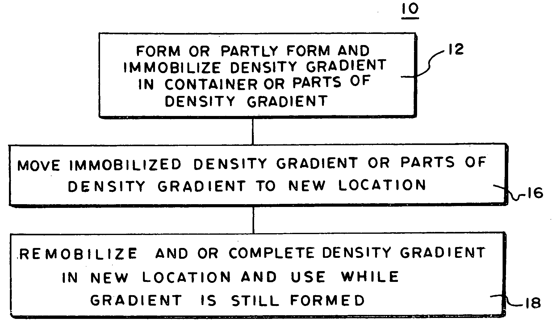
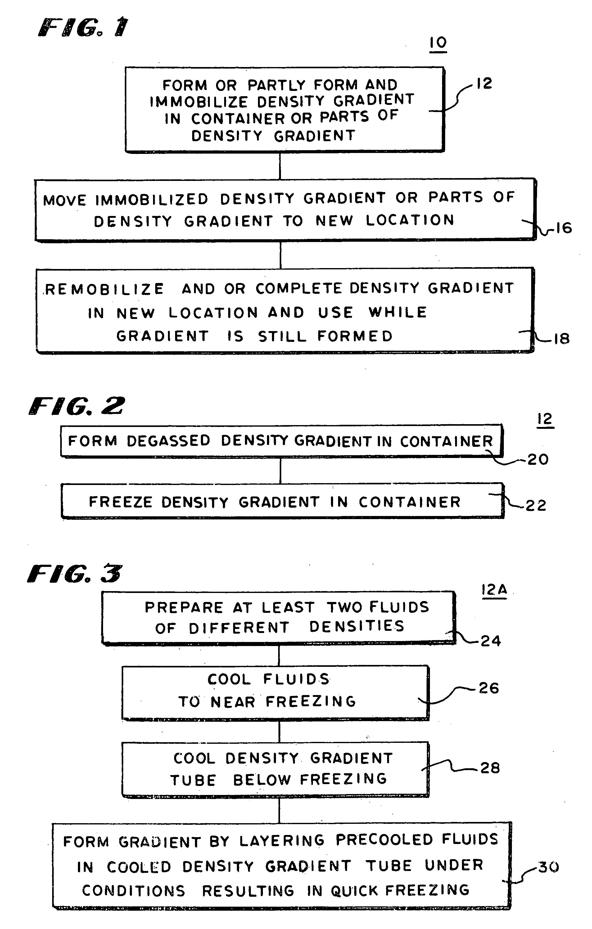
[0021] In FIG. 1, there is shown a block diagram of a process 10 for using density gradient solutions including the step 12 of forming or partly forming and immobilizing density gradient solutions or parts of density gradient solutions, the step 16 of moving the density gradient solution or parts of a density gradient solution to a new location and the step 18 of re-mobilizing the density gradient solutions for use in separating components of a mixture by density. The density gradient solutions may be formed completely prior to immobilization such as by using any of the commercially available automatic density gradient formers. One such gradient density is formerly described in U.S. Pat. No. 4,753,892 to Coombs issued Jun. 28, 1988. Generally the solution must be degassed before immobilization to avoid excessive disturbance of the density gradient solution by bubbles during re-mobilization. Degassing can be accomplished using known degassing techniques such as that disclosed in U.S....


PUM

PropertyMeasurementUnit
densityaaaaaaaaaa
densitiesaaaaaaaaaa
freezing pointaaaaaaaaaa

Abstract

To perform density gradient separation, density gradient columns are prepared at a central location and frozen. They are then taken to other locations while frozen and heated to return the mobility of the density gradient solutions. In this manner, the density gradient solutions can be preserved during travel and for a long period of time, thus removing the need for forming the density gradient solutions at the sites they are to be used and at the time of use and avoiding the need for the purchase of specialized gradient forming equipment in some facilities that use solvent gradient density separations.

Description

BACKGROUND OF THE INVENTION [0001] This invention relates to density gradient tubes, methods of forming, using and transporting density gradient tubes and apparatus for forming, using and transporting gradient tubes from place to place. [0002] Density gradient solution tubes have long been used to separate different density components of mixtures. Apparatuses for automatically forming density gradient solutions such as density gradient solutions of sucrose or cesium chloride solutions and apparatuses for detecting and collecting fractionated components of a mixture separated in a density gradient tube such as by density gradient centrifugation are known. For example, one apparatus for automatically forming a density gradient solution is disclosed in U.S. Pat. No. 4,753,892 and an apparatus for detecting and collecting fractionated components of the sample mixture after density gradient centrifugation is disclosed in U.S. No. Pat. 3,151,639. [0003] In the prior art use of density gra...

Claims


Application Information

Patent Timeline
Patent Type & Authority Applications(United States)
IPC IPC(8): B01F15/04B01L3/14C02F1/22G01N9/36G01N15/04G01N33/49
CPCB01F15/0404B01F15/042B01L3/5021Y10T436/25G01N9/36G01N15/042G01N33/491C02F1/22B01F35/81B01F35/8311
Inventor DAVISON, DALE A.LIESCHESKI, PHILLIP B.
Owner TELEDYNE ISCO INC
Learn More