Office water cooler adapter for use with bagged fluids

Active Publication Date: 2005-05-05
INT PACKAGING INNOVATIONS
View PDF48 Cites 17 Cited by
  • Summary
  • Abstract
  • Description
  • Claims
  • Application Information

AI Technical Summary

Benefits of technology

[0014] In an embodiment a fluid dispensing system comprises a dispensing base; an enclosed chamber positioned interior to the base; a support external to the dispensing base, the support providing support for a bag containing fluid; a fluid passage allowing the fluid in the bag to flow into the enclosed chamber; a vent connecting the enclosed chamber to a space external to the enclosed chamber; and a dispensing valve connected to the enclosed chamber allowing for dispensing from the enclosed chamber. When the dispensing valve is closed, the fluid in the bag will flow through the fluid passage into the enclosed chamber and into the vent, until the fluid level in the vent is the same as the fluid level i

Problems solved by technology

Although conventional domestic water dispensers are widely used, they are deficient in a number of respects.
Due to the weight and size of a bottle holding that amount of water, it is often difficult to invert and properly locate the mouth of the bottle in the chamber without spilling a quantity of the water.
Due to their cost, the water bottles are usually resterilized and reused after an initial use.
As a result, the cost of shipping the empty water bottle back to the supplier for sterilization and reuse are adsorbed by the consumer through increased water costs.
The presence of the neck, however, increases the difficulty in sterilizing the water bottles, since the neck may limit the ability of the sterilizing agents to reach all the interior parts of the bottle, even when large quantities of sterilizing agents are used.
While the use of heat sterilization may overcome this problem to some extent, it is generally not possible to use heat sterilization on plastic bottles.
Although, sterilization using ultraviolet light

Method used


Image

  • Office water cooler adapter for use with bagged fluids
  • Office water cooler adapter for use with bagged fluids
  • Office water cooler adapter for use with bagged fluids

Examples


Embodiment Construction

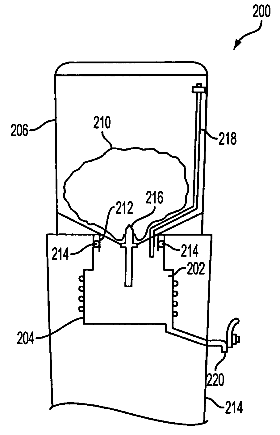
[0013] In light of the prior art and the problems thereof, the fluid dispensing system described herein comprises a support that is preferably used for supporting a collapsible bag containing fluid, the support being designed to be positioned adjacent to a fluid dispensing base. A spike connected to either the support or the dispensing base projects in a direction to enable the spike to puncture a bag containing fluid supported by the support. A fluid passage is provided in the spike to allow fluid to pass from the bag into an enclosed chamber in the dispensing base. The enclosed chamber is connected to the ambient space external to the bag only through a vent channel. In operation, once the bag is spiked, fluid flows from the bag into the chamber until the fluid level in the chamber rises to the level of the vent channel opening and then rises further until the fluid level in the vent channel matches the level of the fluid in the bag. After water is dispensed from the chamber, the ...


PUM


Abstract

A fluid dispensing apparatus comprises a collapsible bag capable of being punctured by and essentially sealed about a spike that has an inlet through which fluid can flow from the bag into a conduit leading to a chamber that is situated within an enclosed chamber in a dispensing base unit. The chamber is connected to a valve positioned outside the enclosed chamber through which fluid can be dispensed from the chamber. The enclosed chamber is vented so that as fluid is dispensed from the chamber, the air pressure in the enclosed chamber is allowed to equalize with the ambient air pressure external to the chamber and the bag.

Description

CROSS REFERENCE TO RELATED APPLICATIONS [0001] This application claims the benefit of U.S. Provisional Patent Applications Nos. 60 / 502,723, filed Sep. 12, 2003, and 60 / 545,155, filed Feb. 17, 2004, the entire disclosures of which are herein incorporated by reference. BACKGROUND OF THE INVENTION [0002] 1. Field of Invention [0003] The present invention relates to a system for dispensing fluids. In particular, the present invention relates to a fluid dispensing system wherein a support structure holds bulk fluid that is transferred to an enclosed chamber in a dispensing base from which chamber the fluid is dispensed. After dispensing air pressure in the enclosed chamber is equalized with the air pressure acting on the bulk fluid. [0004] 2. Description of Related Art [0005] Conventional domestic fluid dispensers used primarily for providing heated or cooled water are usually free standing devices which dispense sterilized or mineral water from large rigid water bottles. The rigid water...

Claims


Application Information

Patent Timeline
IPC IPC(8): B67D7/80B67B7/86B67D3/00B67D99/00
CPCB67B7/28B67D3/0009B67D3/0038B67D3/0032B67D3/0029
Inventor MACLER, HENRY H. IIMACLER, JEFFREY E.AVERY, STEVEN
Owner INT PACKAGING INNOVATIONS
Why Eureka
Try Eureka