
Spurred light source lead wire for handling and for assembling with a filament

a technology of lead wire and filament, which is applied in the direction of electrical apparatus, discharge tube solid thermionic cathodes, and electrolyte emitting electrodes/cathodes, etc., can solve the problems of increasing the cost of the inner light source by the number of filament tubes provided, and accompanied by proportionally higher manufacturing costs

Inactive Publication Date: 2005-05-05
FRIDRICH ELMER G
View PDF40 Cites 13 Cited by
  • Summary
  • Abstract
  • Description
  • Claims
  • Application Information

AI Technical Summary

Benefits of technology

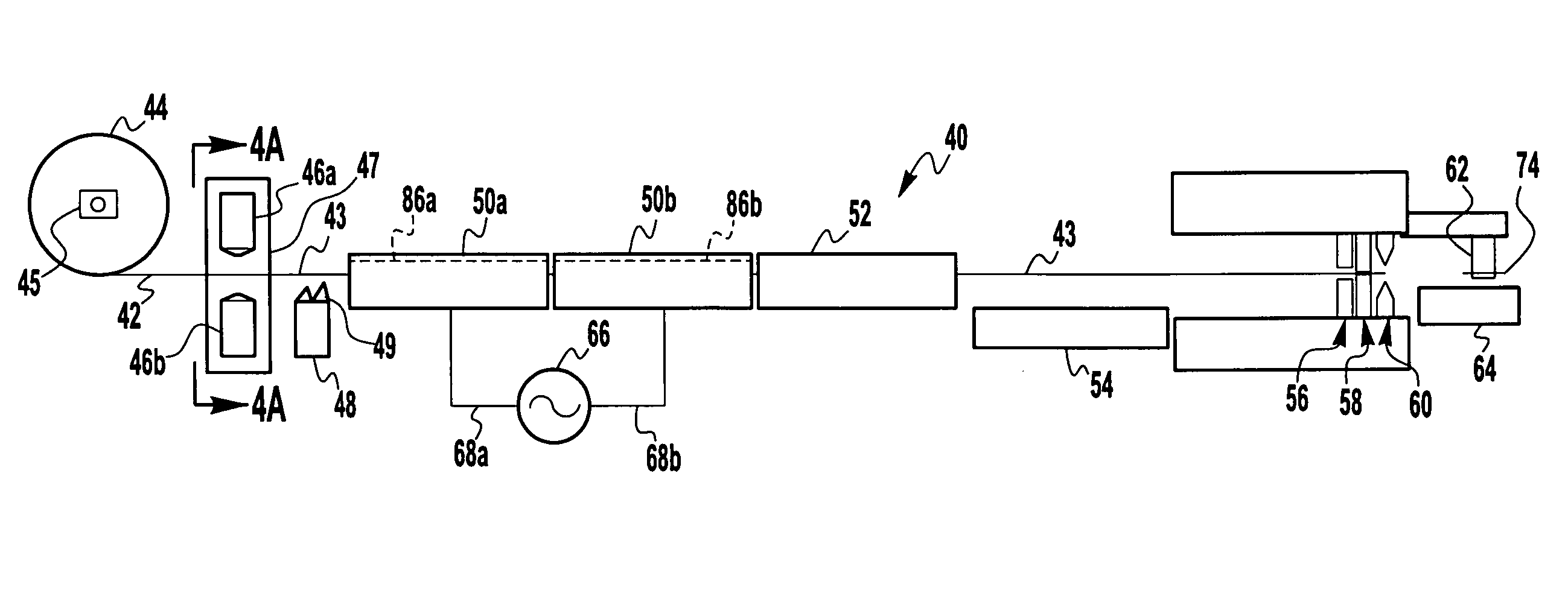
[0022] According to the invention, the filament assembly is such that the first lead wire's inner cut end comprises a single spur near the end of the first lead wire's inner cut end, and a longitudinally directed point at the end of the first lead wire's inner cut end; and the second lead wire's inner cut end comprises a single spur near the end of the second lead wire's inner cut end, and a longitudinally directed point at the end of the second lead wire's inner cut end.
[0023] According to the invention, the filament assembly is such that the first lead wire is a first foliated lead comprising a sealing foil bookended by an inner lead wire outwardly ending in the first lead wire's inner cut end, and an outer lead wire; and the second lead wire is a second foliated lead comprising a sealing foil bookended by an inner lead wire outwardly

Problems solved by technology

Although a variety of compact light sources are available, those with improved energy efficiency (lamp efficacy) are generally accompanied by proportionally higher manufacturing costs, and therefore by higher purchase prices that often outweigh their perceived benefit to ordinary consumers.
This reduces the voltage drop across each filament tube without requiring a transformer, however the cost of the inner light source is multiplied by the number of filament tubes provided.
Incandescent power supplies do not generally provide much ballasting effect, and rely instead on fuses and / or lamp construction to quench an end-of-life arc before it can produce violent failures that may, for example, rupture the filament containing envelope(s)—i.e., to “explode”.
For filament tubes there is a small possibility of non-passive failure due to an arc that overheats the filament tube before the arc can be quenched by a fuse.
Obviously, the heavy glass envelope is much more expensive than a standard bulb.
For lamps that incorporate arc tubes as the light source (e.g., high intensity discharge lamps), non-passive failure is even more of a concern, particularly when the light sources are intended for household use and / or wherever they will not be contained in protective “closed” lighting fixtures.
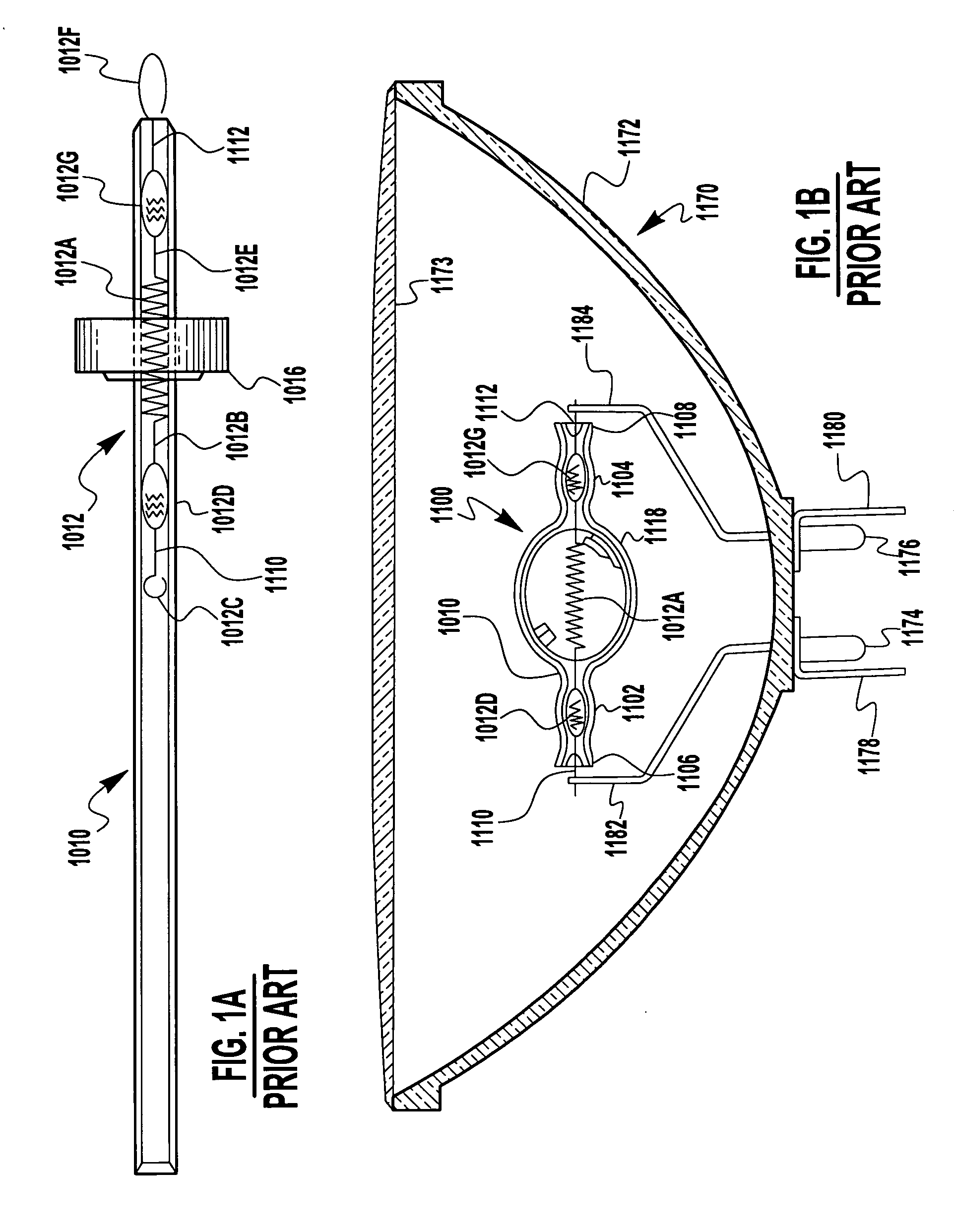
It is known that this spudding process is difficult to automate given that a blunt wire end must be screwed into the coil in a way that expands the coil diameter. FIG. 4 illustrates a single ended filament tube (36) that is also made out of a high temperature glass other than quartz.

Method used


Image

  • Spurred light source lead wire for handling and for assembling with a filament
  • Spurred light source lead wire for handling and for assembling with a filament
  • Spurred light source lead wire for handling and for assembling with a filament

Examples


Embodiment Construction

[0075] The present invention, described hereinbelow in preferred embodiments, comprises manufacturing process steps that improve upon prior art processes for the manufacturing of light sources (both filament tube and arc tube), and lamps employing said light sources, generally by mounting the light source within an outer envelope of a lamp. The improved manufacturing process steps result in improved subassemblies, improved light sources, and improved lamps, all of which are therefore intended to be within the scope of the herein-disclosed invention(s). Many of the inventive improvements are directed toward cost-reducing light source production, especially for lamps that comprise one or preferably two light sources mounted in an outer envelope. In particular, the cost-reduced improved processes can be utilized in the manufacturing of a lamp such as the Gemini lamp wherein two filament tubes are mounted in an outer envelope to form a lamp that is affordable for common household consum...


PUM


Abstract

Manufacturing equipment and manufacturing process steps that improve upon prior art processes for the manufacturing of filament tube and arc tube light sources, their components and subassemblies, and lamps employing said light sources. A double ended, tipless filament tube or arc tube light source incorporates a drawn-down tubular body, and one piece foliated leads with spurs for process handling and for spudding into a filament with stretched-out legs. Bugled ends on the body provide a novel cutoff means, facilitate a flush-fill finishing process, and enhance mounting and support of the light sources in lamps. The foliated leads are made from a continuous length of wire in a process including foil hammering and two-bath AC electrochemical etching. Cost-reduced light source and lamp production enables affordable household consumer lamps, even when containing two series-connected halogen filament tubes. Safety benefits ensue from series connection, especially in combination with disclosed body and filament constructions.

Description

CROSS-REFERENCE TO RELATED APPLICATIONS [0001] This application relates to US applications entitled: LIGHT SOURCE BODIES FOR FILAMENT TUBES AND ARC TUBES, Agent's Docket No. EF-101A; ONE PIECE FOLIATED LEADS FOR SEALING IN LIGHT SOURCES, Agent's Docket No. EF-101B; APPARATUS AND PROCESS FOR FINISHING LIGHT SOURCE FILAMENT TUBES AND ARC TUBES, Agent's Docket No. EF-101D; MOUNTING LIGHT SOURCE FILAMENT TUBES AND ARC TUBES IN LAMPS, Agent's Docket No. EF-101E; and TWO-BATH ELECTROLYSIS, Agent's Docket No. EF-101F; all having filing dates concurrent with that of the present invention. TECHNICAL FIELD OF THE INVENTION [0002] The present invention relates to electric light sources and their manufacturing processes; and, more particularly, to said light sources in the form of a double ended, tipless filament tube or arc tube. BACKGROUND OF THE INVENTION [0003] Although a variety of compact light sources are available, those with improved energy efficiency (lamp efficacy) are generally acco...

Claims


Application Information

Patent Timeline
IPC IPC(8): H01J1/16H01J19/10H01K1/02H01K1/14H01K1/40H01K3/06
CPCH01K1/02H01K3/06H01K1/40
Inventor FRIDRICH, ELMER G.
Owner FRIDRICH ELMER G
Learn More