Plasma display panel provided with an improved electrode

Inactive Publication Date: 2005-05-05
SAMSUNG SDI CO LTD
View PDF15 Cites 9 Cited by
  • Summary
  • Abstract
  • Description
  • Claims
  • Application Information

AI Technical Summary

Benefits of technology

[0007] It is therefore an object of the present invention

Problems solved by technology

Unfortunately, in a PDP design, electrodes must extend outside the display area to form a connection with a driver and/or a power supply.
Excessive electrode presence outside the display area increases

Method used


Image

  • Plasma display panel provided with an improved electrode
  • Plasma display panel provided with an improved electrode
  • Plasma display panel provided with an improved electrode

Examples


Example

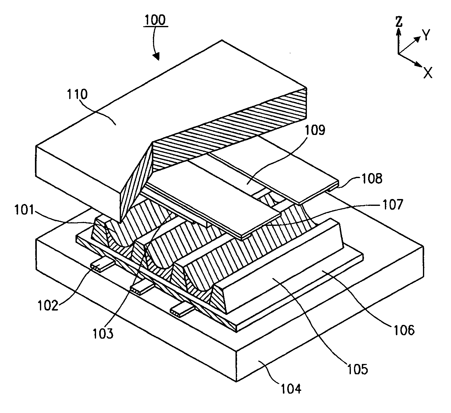
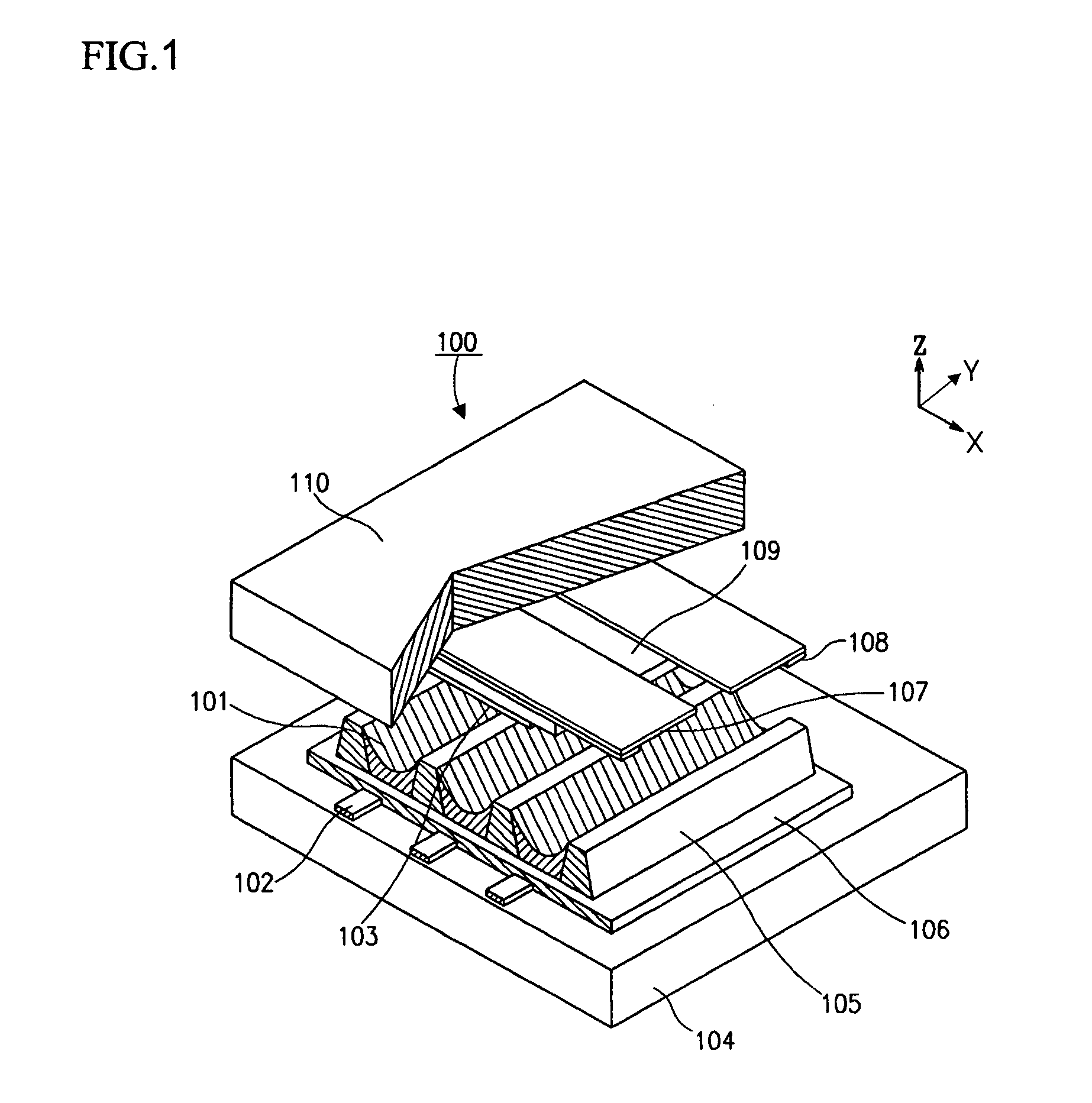
[0021] Turning now to the figures, FIG. 1 is a perspective view of discharge cells in an AC plasma display panel 100. According to the drawing, the PDP 100 includes a rear substrate 104, address electrodes 102 that are formed on the rear substrate 104, a dielectric layer 106 formed on the rear substrate 104 covering the address electrodes 102, a plurality of barrier ribs 105 formed on top of the dielectric layer 106 to maintain a discharge space and to prevent crosstalk between discharge cells, and a phosphor layer 101 formed on the surfaces of the barrier ribs 105.

[0022] A sustain electrode 107 and a scan electrode 108 are on a bottom side or −z side of the front substrate 110 and together form a pair of display electrodes for each discharge cell while extending in a direction that is perpendicular to the direction of the address electrodes 102 formed on the rear substrate 104. A dielectric layer 109 and a protective layer 103 cover the sustain electrodes 107 and the scan electrod...


PUM


Abstract

A plasma display panel minimizing the presence of electrodes outside the display area. In forming the display electrodes across the display, the electrodes extend to only one of the right or left side of the display area. In forming the address electrodes, the electrodes extend to only one of a top or a bottom side of the display area. By so limiting the amount of electrodes outside the display area, less electrode paste is consumed thus reducing expenses and the size of the glass substrate is reduced thus resulting in a more compact display. All of this can be achieved without reducing the display area of the display.

Description

CLAIM OF PRIORITY [0001] This application makes reference to, incorporates the same herein, and claims all benefits accruing under 35 U.S.C. §119 from an application for PLASMA DISPLAY PANEL PROVIDED WITH AN IMPROVED ELECTRODE earlier filed in the Korean Intellectual Property Office on Oct. 31, 2003 and there duly assigned Serial No. 2003-76914. BACKGROUND OF THE INVENTION [0002] 1. Field of the Invention [0003] The present invention relates to a plasma display panel having an improved electrode design, and in particular, to a plasma display panel where the presence of electrodes that are outside the display area is minimized. [0004] 2. Description of the Related Art [0005] A plasma display panel (referred to as a PDP hereinafter) is typically a display device where ultraviolet rays generated by the discharge of a gas excites phosphors to realize visible images. Two electrodes installed in the discharge cell of the PDP makes plasma discharge under a predetermined voltage applied the...

Claims


Application Information

Patent Timeline
IPC IPC(8): H01J17/49
CPCH01J11/48H01J11/12H01J11/26H01J11/34
Inventor MOON, CHEOL-HEERHO, CHANG-SEOK
Owner SAMSUNG SDI CO LTD
Why Eureka
Try Eureka