Drawing method, drawing apparatus and display apparatus

a technology of drawing apparatus and display apparatus, which is applied in the field of drawing method and drawing apparatus, can solve the problems of insufficient filling of droplets, color tone is not uniform in each of the pixel areas, and the peripheral part of the pixel area is particularly affected, so as to prevent the scattering of shot drops and achieve favorable display

Inactive Publication Date: 2005-05-05
KATEEVA
View PDF6 Cites 17 Cited by
  • Summary
  • Abstract
  • Description
  • Claims
  • Application Information

AI Technical Summary

Benefits of technology

[0019] Since the shot drops with the filter or luminescence material are formed on the pixel areas by using the aforementioned drawing method or drawing apparatus, the filter or luminescence material can be efficiently provided in the pixel areas of the display apparatus. Further, a display apparatus capable of preventing the scattering of shot drops in the arrangement in each pixel area and capable of providing a favorable display can be obtained.

Problems solved by technology

In the conventional method, however, there is a problem in that the periphery of the pixel areas, a corner part thereof in particular, is not sufficiently filled with the droplets.
In other words, the color tone is not uniform in each of the pixel areas.

Method used


Image

  • Drawing method, drawing apparatus and display apparatus
  • Drawing method, drawing apparatus and display apparatus
  • Drawing method, drawing apparatus and display apparatus

Examples


embodiment 1

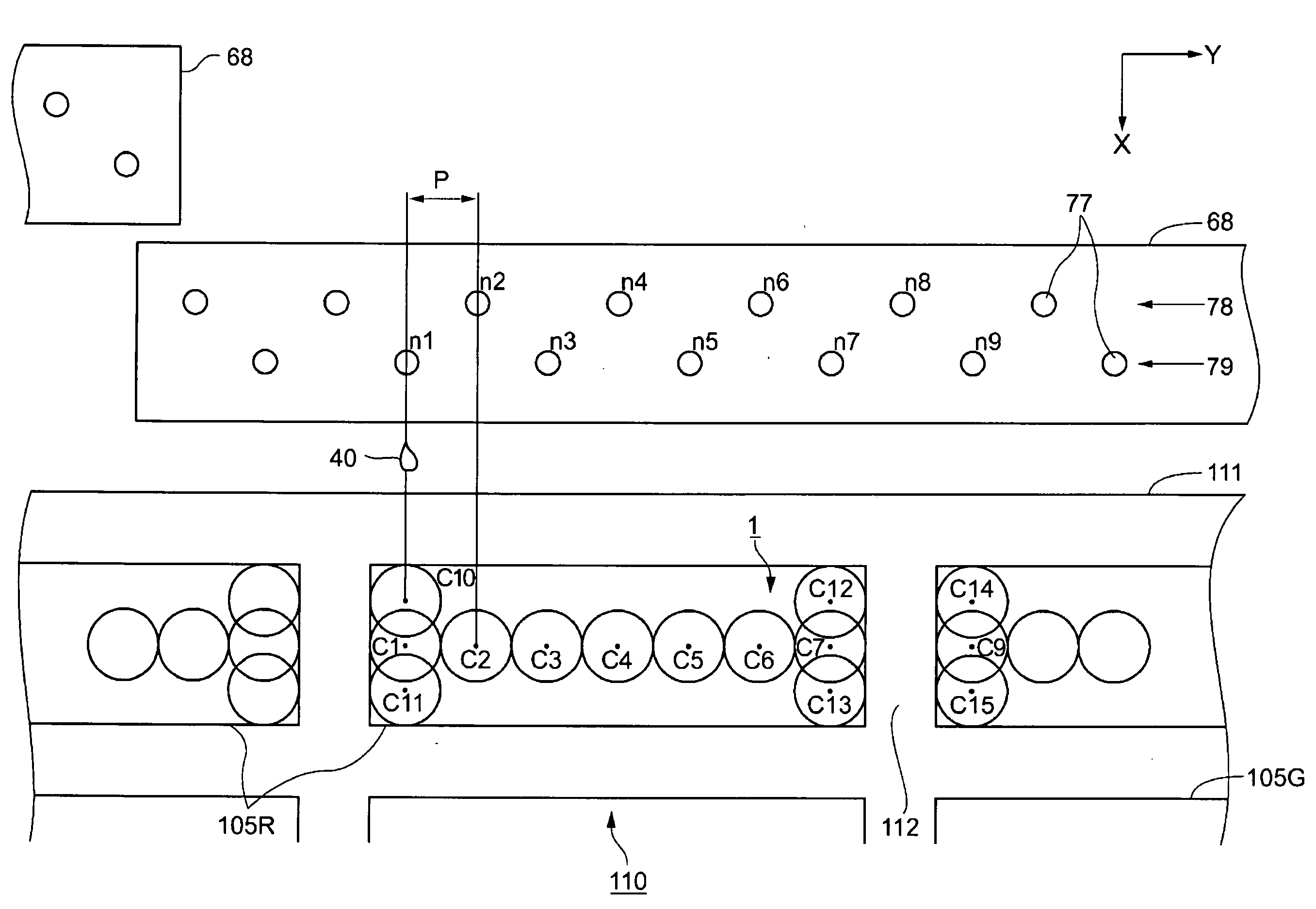
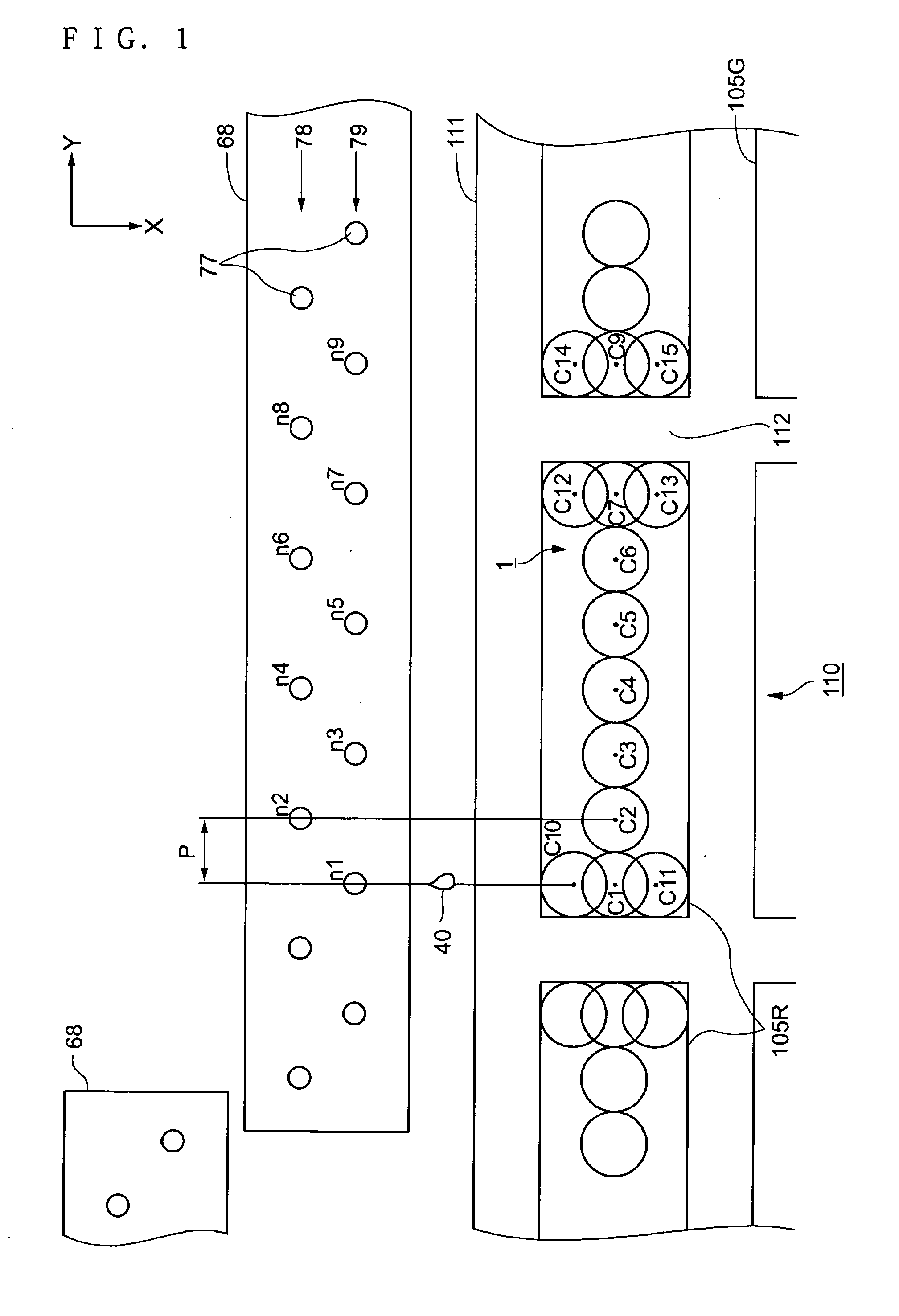
[0032] A method of ejecting and coating a filter material as droplets from the nozzles of a drawing apparatus to the pixel areas 105 of the color filter 110 by using a drawing method according to the invention will now be described. In the color filter 110, as shown in FIG. 1, an array of pixel areas 105R on which the red (R) filter material is coated is arranged on the filter substrate 111. In the drawing apparatus, nozzles 77 are arranged to form two nozzle arrays 78 and 79 which run parallel to the y-axis direction of an ejecting head 68. The nozzles 77 in the nozzle array 78 and the nozzles 77 in the nozzle array 79 are shifted from each other in the y-axis direction, and a nozzle pitch in the y-axis direction of the ejecting head 68 is P. A plurality of ejecting heads 68 is arranged in the y-axis direction so that the nozzles 77 extend sequentially in the y-axis direction at a pitch P.

[0033] With this constitution, either the pixel areas 105R or the ejecting head 68 shifts rel...

embodiment 2

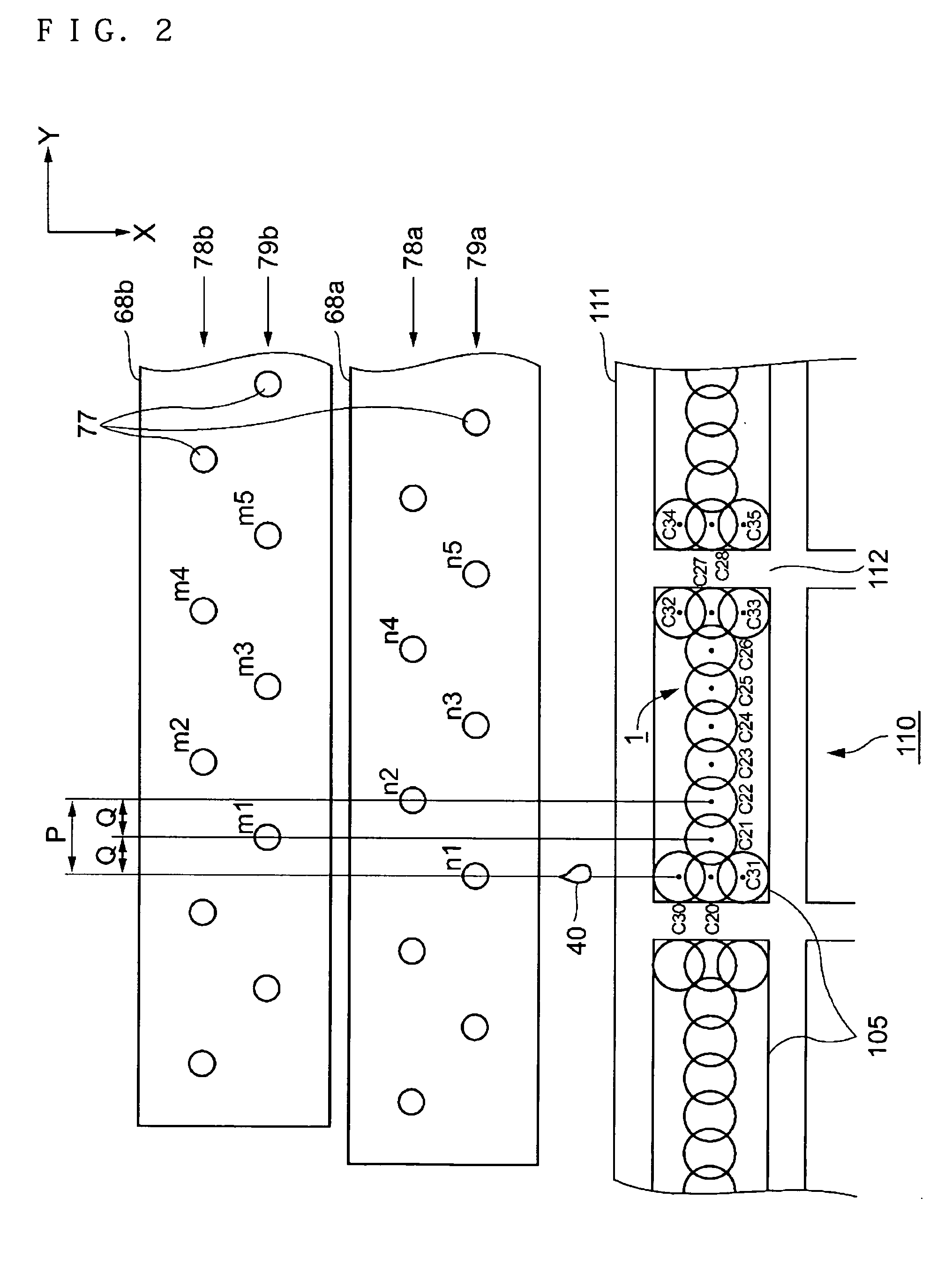
[0043] Next, the case will be described where the same ejecting head 68 is used and the droplets 40 are arranged more minutely with pitch P narrowed. In this case, as shown in FIG. 2, two ejecting heads 68a and 68b having nozzles 77 at pitch P are arranged in parallel and shifted from each other by an amount Q which is half of the pitch P. Each of the two ejecting heads 68a and 68b corresponds to one ejecting head 68 in Embodiment 1.

[0044] Here, assuming that the nozzle pitch P of the ejecting heads 68a and 68b in the y-axis direction is 60 μm and that both ejecting heads 68a and 68b constitute one ejecting head group, the nozzle pitch Q is set to be 30 μm. The space between each head array, that is, between nozzle arrays 78a and 79a of the ejecting head 68a, between nozzle arrays 78b and 79b of the ejecting head 68b and between nozzle arrays 78a and 79b is 80 μm. The volume of the droplets 40 ejected from the ejecting head group is set at 4 pl. The outer peripheral diameter Φ of t...


PUM


Abstract

A method is provided to reliably form shot drops on all of a plurality of pixel areas. The method comprises a step of forming a plurality of shot drops by ejecting droplets from a plurality of nozzles of a drawing apparatus to a plurality of pixel areas on a substrate. The step of forming the plurality of shot drops includes a step of forming additional shot drops near predetermined ones of the plurality of shot drops.

Description

RELATED APPLICATIONS [0001] This application claims priority to Japanese Patent Application No. 2003-348423 filed Oct. 7, 2003 which is hereby expressly incorporated by reference herein in its entirety. BACKGROUND [0002] 1. Technical Field [0003] The present invention relates to a drawing method and a drawing apparatus operating in an ink-jet mode for ejecting droplets of a liquid material, and to a display apparatus. [0004] 2. Background Art [0005] As a conventional method of forming a filter material and the like for a color filter in the pixel areas on a substrate on which droplets are ejected by using a drawing apparatus in an ink-jet mode, there is a method in which droplets (a material for a color filter) are sequentially arranged in an array in pixel areas of each color constituting the color filter. [0006] In the conventional method, however, there is a problem in that the periphery of the pixel areas, a corner part thereof in particular, is not sufficiently filled with the ...

Claims


Application Information

Patent Timeline
Patent Type & Authority Applications(United States)
IPC IPC(8): B41J2/11B41J2/01B41J2/15G02B5/20H01J9/20H01L27/32H01L51/00H01L51/56H05K3/12
CPCB41J2/15B41J2202/09B41J2202/20H01J9/205H05K3/1241H01L27/3211H01L51/0005H01L51/56H01J2211/44H10K59/35H10K71/135H10K71/00B41J2/01
Inventor KATO, TSUYOSHIKURIBAYASHI, MITSURU
Owner KATEEVA
Why Eureka
Try Eureka