Objective lens unit, objective lens insertion tool, microscope, objective optical system fixing device, and microscope system

a technology of optical system and fixing device, which is applied in the field of optical system fixing device, microscope, and objective lens unit, can solve the problems of inability to align the microscope, inability to in vivo examine the various organs of small experimental animals, rats and mice,

Inactive Publication Date: 2005-05-05
OLYMPUS CORP
View PDF12 Cites 22 Cited by
  • Summary
  • Abstract
  • Description
  • Claims
  • Application Information

AI Technical Summary

Benefits of technology

[0015] It is a further object of the present invention to prevent the intrusion of foreign objects into the subject under examination, and to provide a microscope to which such an objective lens unit is attached and a microscope system including such a microscope.
[0016] It is yet a further object of the...

Problems solved by technology

In cases where the sample is tissue or the like of a small animal, such alignment is particularly difficult.
Furthermore, microscopes including conventional confocal laser-scanning microscopes are not designed for in vivo examination of various organs of small experimental animals, such as rats and mice.
Therefore, in cases where vibration occurs due to the pulsation of blood vessels or the like, there are conceivably disadvantages such as images of the subject site under examination becoming blurred or the focal point becoming out of focus as a result of movement in th...

Method used


Image

  • Objective lens unit, objective lens insertion tool, microscope, objective optical system fixing device, and microscope system
  • Objective lens unit, objective lens insertion tool, microscope, objective optical system fixing device, and microscope system
  • Objective lens unit, objective lens insertion tool, microscope, objective optical system fixing device, and microscope system

Examples


first embodiment

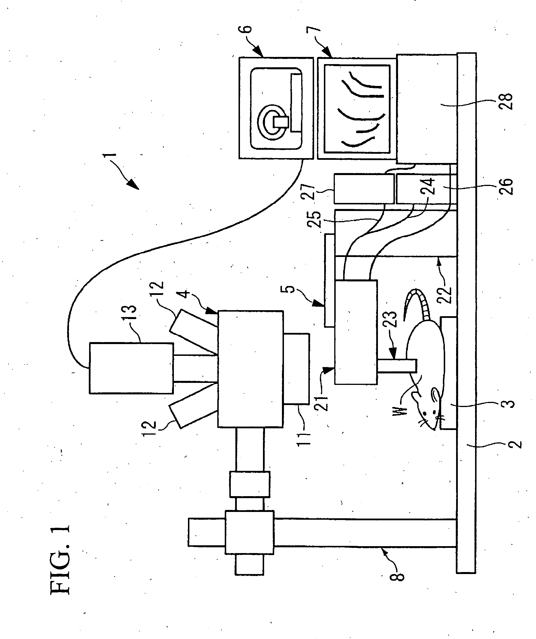
[0086]FIG. 1 shows the schematic configuration of a microscope system according to the present invention.

[0087] As shown in FIG. 1, a microscope system 1 includes a stage 3 on a platform 2, and above the stage 3, a binocular stereo microscope 4 for observing an upright image of a subject W over a relatively wide field of view is provided. Between the stage 3 and the binocular stereo microscope 4, a microscope 5 (hereinafter referred to as a micro microscope) for observing the subject W at a relatively high magnification is provided in a freely movable manner.

[0088] The binocular stereo microscope 4 has an objective lens 11 and eyepieces 12 attached thereto, and inside, an ocular lens, an image-forming lens, etc. (not shown in the drawing) are disposed. Two eyepieces 12 are provided, one for each of the left and right eyes, and the optical axes of the individual eyepieces 12 are adjusted so as to be coincident at the surface of the subject W under examination. Furthermore, a CCD (Ch...

fourth embodiment

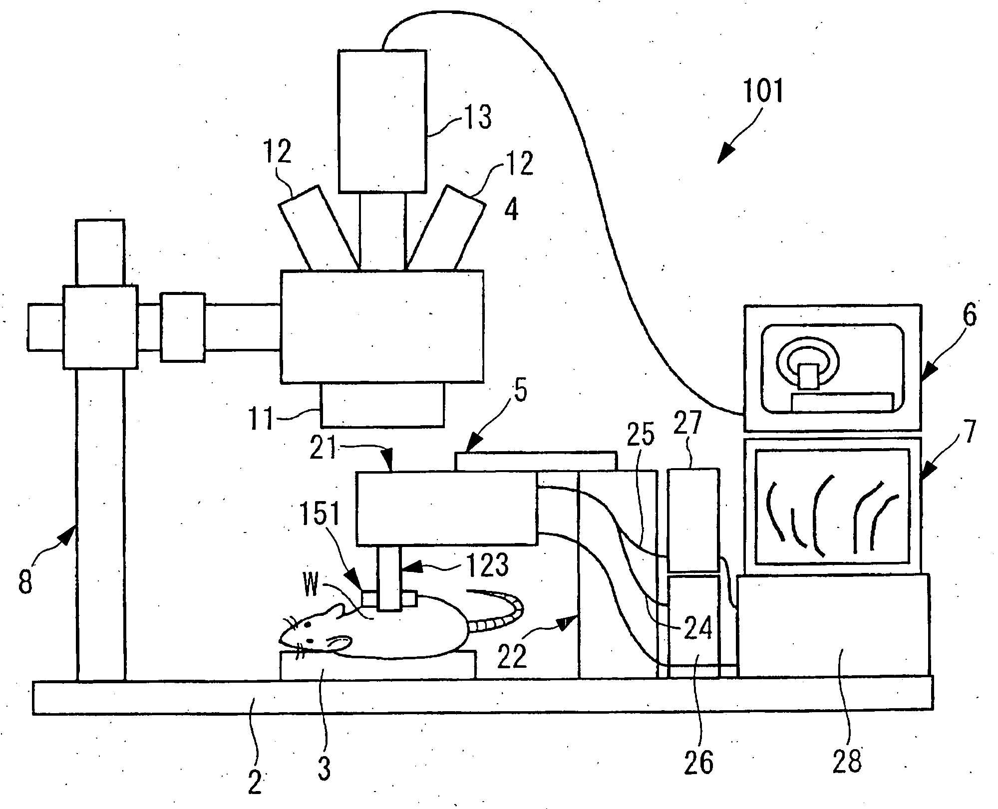
[0150] The structure of a microscope system is schematically shown in FIG. 11.

[0151] A microscope system 101 of the present embodiment has the same configuration of the microscope system of the first embodiment except that an objective lens unit 123 that differs from the objective lens unit 23 used in the first embodiment is attached to the lower surface of the head unit 21. An objective lens insertion tool 151, into which the end of the objective lens unit 123 is inserted and fixed, is attached to the subject W under examination.

[0152] As shown in FIG. 12 and FIG. 13, the objective lens unit 123 has a structure in which a plurality of objective lenses 142 are held inside a frame part 141. The frame part 141 has a step so as to reduce the diameter thereof, and at the end of a large-diameter frame base part 143, which is attached to a mounting part of the head unit 21, a frame base part 144 that is smaller in diameter than the frame base part 143 and that is mainly inserted inside ...

fifth embodiment

[0173] Next, the present invention will be described with reference to the drawings. Elements having the same structure as those of the preceding embodiments are given the same reference numerals, and any description duplicating the preceding embodiments is omitted.

[0174] The microscope system of this embodiment is characterized in that the frame part of the objective lens is L-shaped.

[0175] As shown in FIG. 14, an objective lens unit 173 has a frame part 174 holding a plurality of objective lenses 142. A frame part 174 is formed of an L-shaped frame base part 175 and a frame tip part 144 extending from the frame base part 175. The frame base part 175 is formed of a vertical part 176 continuous with the frame tip part 144 and extending upwards, and a horizontal part 177 extending horizontally from near the upper end of the vertical part 176. A mounting part 146, which is used when attaching to the head unit 21, is provided at the end of the horizontal part 177. In this type of obje...


PUM


Abstract

The invention aims to make it unnecessary to reposition an objective lens when repeatedly carrying out examinations. It is possible to carry out in vivo examination of tissue such as cells and muscle tissue or various internal organs, such as the heart, liver, and so forth, of mammals, especially small experimental animals, over a comparatively long period of time. A microscope system having an objective optical system unit and a structure or member for fixing the objective optical system unit to a living body is provided.

Description

BACKGROUND OF THE INVENTION [0001] 1. Field of the Invention [0002] The present invention relates to objective lens units disposed at the subject side in optical apparatuses, to objective lens insertion tools for inserting objective lens units of optical apparatuses, to microscopes provided with such objective lens units or objective lens insertion tools, to microscope systems including such microscopes, and to objective optical system fixing devices. [0003] Priority is claimed on Japanese Patent Applications Nos. 2003-357577, 2003-363501, and 2004-72236, the contents of which are incorporated herein by reference. [0004] 2. Description of Related Art [0005] Conventionally, a confocal laser-scanning microscope is a known apparatus for obtaining surface and tomographic images of samples of living cells and tissue in order to observe cellular function or the like, by illuminating a sample of a living body with excitation light from the surface thereof and by selectively detecting fluor...

Claims


Application Information

Patent Timeline
IPC IPC(8): G02B21/26G02B23/24
CPCG02B21/26G02B23/2476
Inventor TOKUDA, KAZUNARIHORII, AKIHIROKUMADA, YOSHIYUKIHARA, MITSUHIROHIRATA, TADASHIFUKUYAMA, HIROYA
Owner OLYMPUS CORP
Why Eureka
Try Eureka