Light deflection element and light source apparatus using the same

a technology of light source apparatus and deflection element, which is applied in the direction of mechanical apparatus, lighting and heating apparatus, instruments, etc., can solve problems such as complicated formation

Inactive Publication Date: 2005-05-05
LMS
View PDF4 Cites 94 Cited by
  • Summary
  • Abstract
  • Description
  • Claims
  • Application Information

AI Technical Summary

Benefits of technology

[0008] According to the present invention, there is provided a light deflector comprising a light entrance surface on which light is incident and a light exit surface located on an opposite side relative to the light entrance surface and allowing the incident light to exit therefrom, wherein the light entrance surface is formed with a plurality of elongated prisms arrayed substantially parallel to each other and each composed of two prism surfaces, at least one of the prism surfaces of each of the elongated prisms comprises at least two flat surfaces having mutually different inclination angles, any one of the flat surfaces located on a side closer to the light exit surface has a larger inclination angle, and a difference between the inclination angle of one of the flat surfaces closest to the light exit surface and the inclination angle of the other one of the flat surfaces farthest from the light exit surface is 15 degrees or less.

Problems solved by technology

This formation is complicated.

Method used


Image

  • Light deflection element and light source apparatus using the same
  • Light deflection element and light source apparatus using the same
  • Light deflection element and light source apparatus using the same

Examples


example 1

[0162] Using an acrylic resin (Acrypet VH5#000 produced by Mitsubishi Rayon Co., Ltd.), a light guide having one surface in the form of a mat surface was prepared by injection molding. The light guide had a wedge-plate shape having a size of 216 mm×290 mm with thicknesses 2.0 mm-0.7 mm. On a mirror finished surface of this light guide was formed a prism layer made of an acrylic ultraviolet curing resin and having elongated prisms successively arrayed side by side at a pitch of 50 μm and with a prism vertical angle of 100 degrees and each extending in parallel to a side of 216 mm (short side) of the light guide. A cold-cathode tube was disposed along one side end surface (end surface on the side with the thickness 2.0 mm) corresponding to a side of 290 mm (long side) of the light guide, while the cold-cathode tube was covered with a light source reflector (silver reflection film produced by Reikosha). Further, light diffusion reflection films (E60 produced by Toray Industries, Inc.) ...

example 2

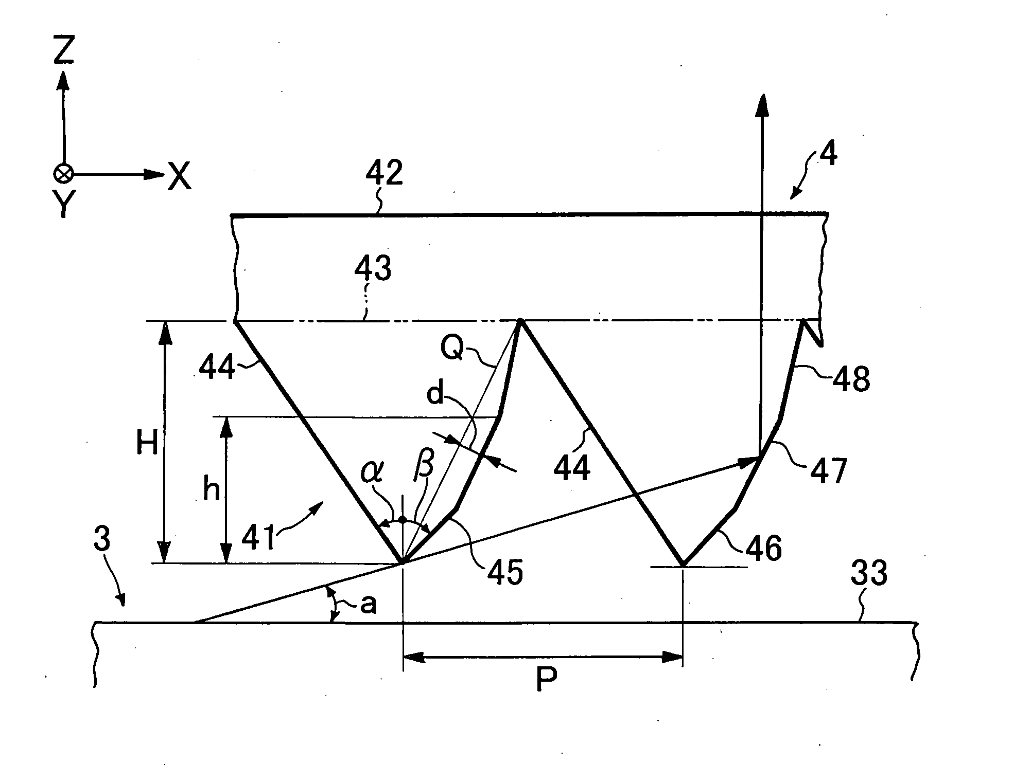
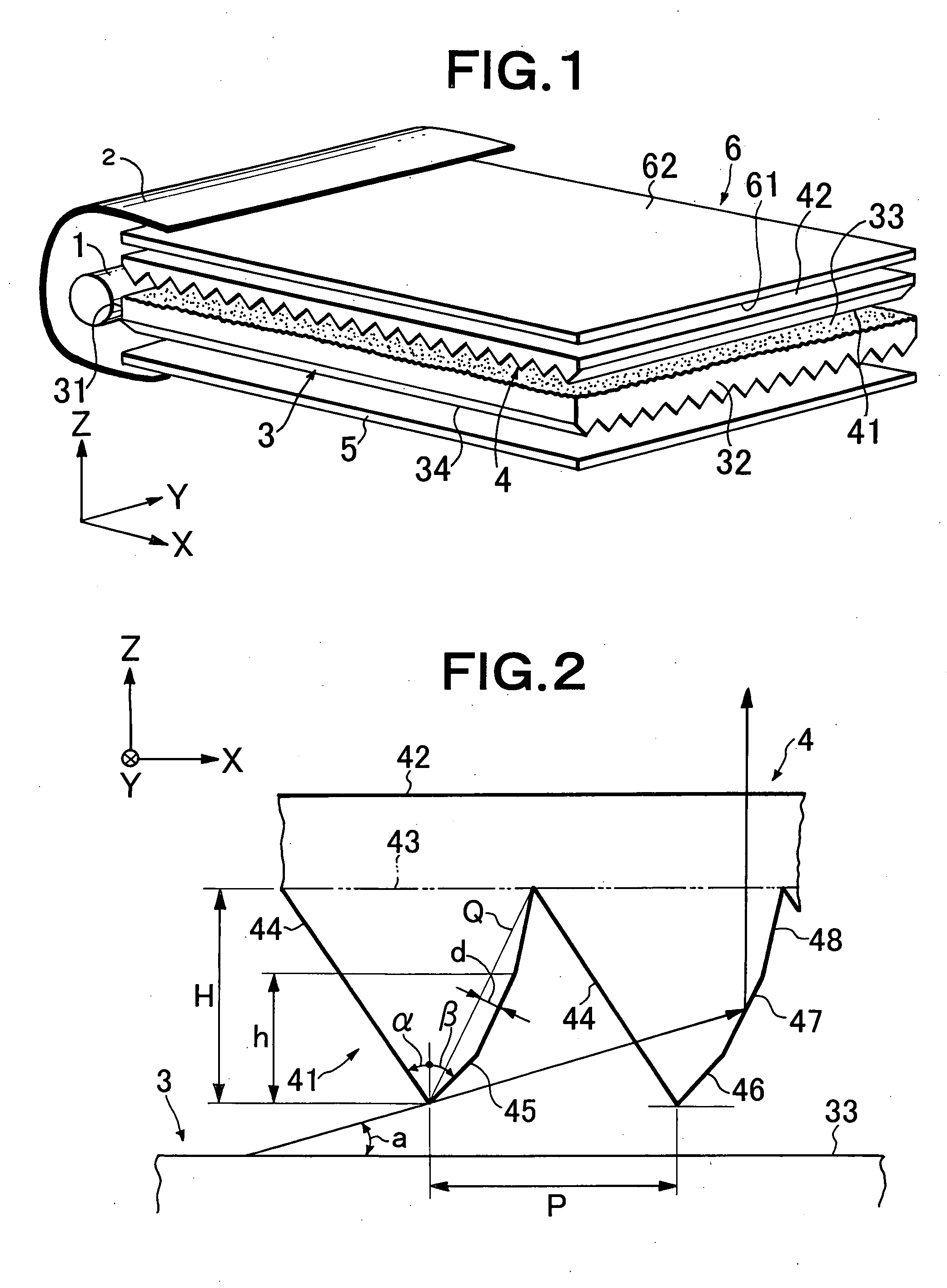
[0165] A prism sheet was prepared like in Example 1 except that, as shown in Table 3, a second prism surface of each elongated prism was formed by seven flat surfaces (areas 1, 2, . . . 7, in order from the side of the prism vertex portion), i.e. a flat surface (β=34.8 degrees) formed from the prism vertex portion to a height 16 μm of the elongated prism and having an inclination angle of 55.2 degrees, and six flat surfaces of the same width formed from the height 16 μm of the elongated prism to the prism bottom portion in order of inclination angles of 55.5 degrees, 56.2 degrees, 57.0 degrees, 57.8 degrees, 58.4 degrees, and 59.4 degrees from the side closer to the prism vertex portion. A ratio (d / P) of a maximum distance (d) between the second prism surface of the prism sheet and a virtual flat plane for the second prism surface relative to the pitch (P) of the elongated prisms was 1.10%.

[0166] The obtained prism sheet was placed in such a manner that the elongated prism formed s...

example 3

[0167] A prism sheet was prepared like in Example 1 except that, as shown in Table 3, a second prism surface of each elongated prism was formed by two flat surfaces and one convex curved surface (areas 1, 2, and 3, in order from the side of the prism vertex portion), i.e. a flat surface (β=33.6 degrees) formed from the prism vertex portion to a height 10.6 μm of the elongated prism and having an inclination angle of 56.4 degrees, a flat surface formed from the height 10.6 μm to a height 21.3 μm of the elongated prism and having an inclination angle of 56.8 degrees, and a convex curved surface (inclination angle=59.2 degrees) formed from and above the height 21.3 μm of the elongated prism and having a circular-arc shape in section with a radius of curvature of 400 μm. A ratio (d / P) of a maximum distance (d) between the second prism surface of the prism sheet and a virtual flat plane for the second prism surface relative to the pitch (P) of the elongated prisms was 1.03%.

[0168] The o...


PUM


Abstract

A surface light source apparatus includes a primary light source (1), an optical guide (3) for guiding light emitted from the primary light source and having a light incoming surface (31) and a light outgoing surface (32), a light deflection element (4) arranged adjacent to the light outgoing surface of the optical guide and having a light incoming surface (41) and a light outgoing surface (42), and a light diffusion element (6) arranged adjacent to the light outgoing surface of the light deflection element. The light incoming surface (41) of the light deflection element has a plurality of prism strings arranged substantially parallel to each other and each having two prism surfaces. At least one of the prism surfaces of these prism strings has a prism surface consisting of at least two planes having different inclination angles. As the plane approaches the light outgoing surface, the inclination becomes larger. The difference between the inclination angle of the plane nearest to the light outgoing surface and that of the plane farthest from the light outgoing surface is 15 degrees or below.

Description

TECHNICAL FIELD [0001] The present invention relates to an edge-light type light source device or light source apparatus forming a liquid crystal display device or the like that is used as a display portion in a notebook personal computer, a liquid crystal television, a portable telephone (cellular phone), a portable information terminal (personal digital assistants), or the like, and to a light deflector or light deflection element for use in the light source device. Particularly, the present invention relates to an improvement in the light deflector disposed adjacent to a light outgoing surface of a light guide of the light source device. BACKGROUND ART [0002] In recent years, color liquid crystal display devices have been widely used in various fields as monitors of portable notebook personal computers, personal computers, and so forth, or as display portions of liquid crystal televisions, video-combined liquid crystal televisions, portable telephones, portable information termin...

Claims


Application Information

Patent Timeline
Patent Type & Authority Applications(United States)
IPC IPC(8): F21V8/00G02B5/04G02B6/00
CPCG02B5/045G02B6/0053G02B6/0038G02B5/04G02F1/1335
Inventor YAMASHITA, TOMOYOSHICHIBA, ISSEI
Owner LMS
Why Eureka
Try Eureka