Converging substrate, electro-optic device, substrate for electro-optic device, projector, and electronic apparatus

a technology of electro-optic devices and substrates, applied in the direction of optics, color television details, instruments, etc., can solve the problems of reducing the efficiency of light utilization in the projection optical system, reducing contrast, and increasing the ray angle of light rays entering the liquid crystal layer, so as to achieve bright display, prevent the deterioration of the electro-optic device due to the irradiation of light rays, and increase the contrast

Inactive Publication Date: 2007-08-09
SEIKO EPSON CORP
View PDF8 Cites 14 Cited by
  • Summary
  • Abstract
  • Description
  • Claims
  • Application Information

AI Technical Summary

Benefits of technology

[0007] An electro-optic device according to an aspect of the invention is an electro-optic device having a plurality of pixels arranged in a matrix pattern, including a converging substrate formed of a transparent substrate having groove-shaped prism elements formed in an array pattern, wherein the prism elements are arranged along boundary areas of the pixels, the prism elements each include a plurality of beveled portions arranged on side walls thereof in the direction of the thickness of the converging substrate, and the prism elements each include beveled portions whose inclination angle with respect to the direction of the normal line of the converging substrate is smaller than that of other beveled portions on an opening end side of each of the prism elements.
[0008] With the provision of the converging substrate having a configuration in which the plurality of beveled portions having different inclination angles are arranged on the side walls of each of the prism elements and the beveled portions having a small inclination angle are formed on the opening end side of the prism element, the beveled portions which extend in the direction close to the direction parallel with the normal line are provided on the opening end side while tapering toward the distal end of the prism element. With the provision of the beveled portions having a small inclination angle, the incident angle of light rays being reflected by the beveled portions and entering the pixels is prevented from increasing excessively, and hence a display contrast is increased. Through decrease of the angle of the beveled portions on the opening end side with respect to the normal line, the reflected light rays from the beveled portions proceed toward portions in the vicinity of the boundaries of the pixels. Therefore, the distribution of light rays entering the pixel is uniformized, so that deterioration of the electro-optic device due to the irradiation of the light rays may be prevented. In addition, since the beveled portions having a larger inclination angle are formed on the side of the distal end of the prism element, the light rays entering the boundary areas of the pixels may be guided to the pixels, and hence bright display is obtained.
[0009] In the electro-optic device according to an aspect of the invention, preferably, the beveled portions arranged on the opening end side of the prism element are formed so as to extend in parallel with the normal line of the converging substrate. In this configuration, the incident angle of the light rays reflected by the beveled portions arranged on the opening end side of the prism element with respect to the pixels is reduced, and hence improvement of the contrast is achieved.
[0010] In the electro-optic device according to an aspect of the invention, preferably, light-shielding members are provided on a surface of the converging substrate at positions to cover the opening ends of the prism elements. In this configuration, the light rays reflected by the prism elements cannot enter the light-shielding members easily, so that the light amount and hence the light amount outputted from the converging substrate and entering into the pixels may be increased. Since the light-shielding members are provided directly on the surface of the converging substrate without the intermediary of other members, the electro-optic device may be manufactured in a simple process at low cost.
[0011] In the electro-optic device according to an aspect of the invention, a configuration in which a resin layer is formed on the opening ends side of the prism elements is also applicable. In this configuration, since the rough surface of the transparent substrate caused by the prism elements may be flattened by the resin layer, so that the converging substrate may be conveniently used as a substrate constituting the electro-optic device.
[0012] An electro-optic device according to an aspect of the invention, which is also applicable, is an electro-optic device having a plurality of pixels arranged in a matrix pattern, including a converging substrate formed of a transparent substrate having groove-shaped prism elements formed in an array pattern, wherein the prism elements are arranged along boundary areas of the pixels, the prism elements each include a plurality of beveled portions arranged on side walls thereof in the direction of the thickness of the converging substrate, and wherein, assuming that light rays reflected by the beveled portions formed on an opening end side of the prism element are first reflected light; rays and the light rays reflected by the other beveled portions are second reflected light rays from among the light rays entering the beveled portions from the side opposite from the plurality of pixels at the same incident angle, and the angle of the first reflected light rays with respect to the normal line of the surface of the converging substrate on which the prism elements are formed is a first angle, and the angle of the second reflected light rays with respect to the normal line is a second angle, the angle of the first angle is smaller than the angle of the second angle.

Problems solved by technology

However, there is a problem that ray angles of light rays entering a liquid crystal layer are increased because incident light rays are refracted by the microlens and hence the contrast is lowered.
There is another problem that the efficiency for light utilization in a projection optical system is lowered since the light rays having a ray angle exceeding the numerical aperture (NA) of the projection optical system is not used for display.
In addition, since the convergence is performed by a lens, concentration of the light rays occurs as a result of convergence, so that generation of luminance distribution in a pixel as well as deterioration of light resistance due to the convergence may be resulted.

Method used


Image

  • Converging substrate, electro-optic device, substrate for electro-optic device, projector, and electronic apparatus
  • Converging substrate, electro-optic device, substrate for electro-optic device, projector, and electronic apparatus
  • Converging substrate, electro-optic device, substrate for electro-optic device, projector, and electronic apparatus

Examples


Embodiment Construction

Projector

[0056] Referring now to the drawings, embodiments of the invention will be described.

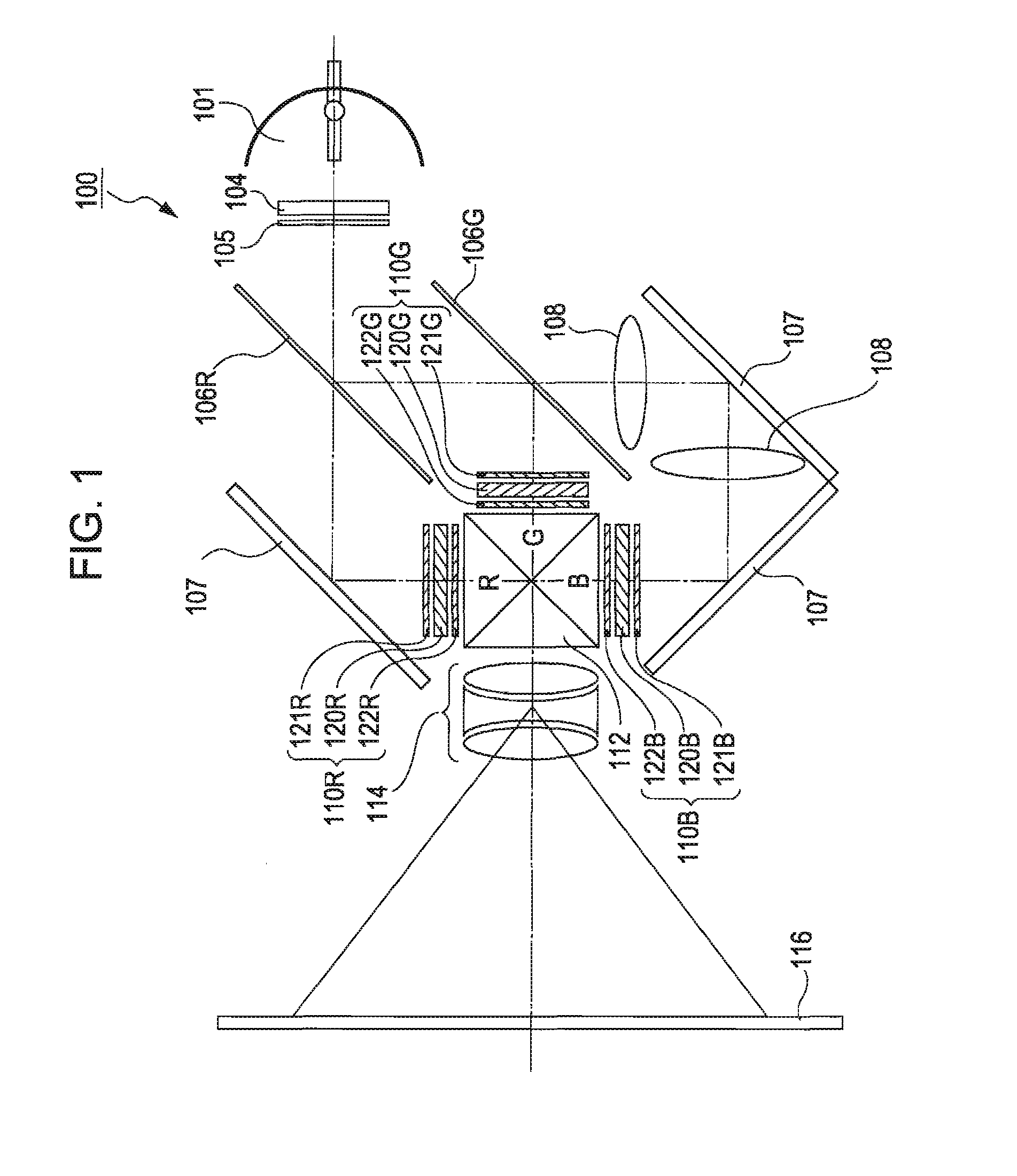
[0057]FIG. 1 illustrates a schematic configuration of a projector according to an embodiment of the invention. As shown in FIG. 1, an extra-high pressure mercury lamp 101 as a light source supplies a light ray including red light as first-color light (hereinafter referred to as “R-light”), green light as second-color light (hereinafter referred to as “G-light”), and a blue light as third-color light (hereinafter referred to as “B-light”). An integrator 104 uniformizes distribution of illumination intensity of light rays supplied from the extra-high pressure mercury lamp 101. The light ray whose distribution of illumination intensity is uniformized by the integrator 104 is converted into a linear polarized light having a specific direction of oscillation, for example, into s-polarized light, by a polarized light converting element 105. The light converted into the S-polarized light enters...


PUM


Abstract

An electro-optic device having a plurality of pixels arranged in a matrix pattern, including: a converging substrate formed of a transparent substrate having groove-shaped prism elements formed in an array pattern, wherein the prism elements are arranged along boundary areas of the pixels, wherein the prism elements each include a plurality of beveled portions arranged on side walls thereof in the direction of the thickness of the converging substrate, and wherein the inclination angle of the beveled portions arranged on an opening end side of each of the prism elements with respect to the normal line of the converging substrate on which the prism elements are formed is smaller than the inclination angle of the other beveled portions.

Description

BACKGROUND [0001] 1. Technical Field [0002] Several aspects of the present invention relate to a converging substrate, an electro-optic device, a substrate for an electro-optic device, a projector, and an electronic apparatus. [0003] 2. Related Art [0004] An electro-optic device includes circuits for driving pixels in an image display area and, in particular, a liquid crystal device includes various wirings and switching devices such as TFT (Thin Film Transistor) Therefore, the ratio (aperture ratio) of an area from which. light rays actually go out (an area which contributes to a display) with respect to a pixel area is, for example, approximately 70%, and hence only the light amount corresponding to this aperture ratio is used for the display. Therefore, improvement of the efficiency for light utilization by providing microlenses corresponding to the respective pixels of the liquid crystal device and converging light rays supplied from a light source toward aperture areas of the p...

Claims


Application Information

Patent Timeline
Patent Type & Authority Applications(United States)
IPC IPC(8): G02F1/03
CPCG02F1/133526H04N9/3197H04N9/3102
Inventor KAMIJIMA, SHUNJIMIZUSAKO, KAZUHISAINOGUCHI, MAKOTO
Owner SEIKO EPSON CORP
Why Eureka
Try Eureka