
Bearing or drive assembly with coated elements

a technology of coating elements and drive assemblies, which is applied in the direction of bearings, shafts, ball bearings, etc., can solve the problems that ball bearings may also include very expensive bearing elements of ceramic materials, and achieve the advantages of hydrolytic stability, simple and more cost-favorable production, and thin formation of polyimide coatings

Inactive Publication Date: 2005-05-05
GORLACH BERND
View PDF11 Cites 2 Cited by
  • Summary
  • Abstract
  • Description
  • Claims
  • Application Information

AI Technical Summary

Benefits of technology

[0004] The fact that at least one bearing or drive element comprises a polyimide coating on a carrier material permits reducing the lubricant needs and thus the operating costs to a great extent in comparison with lubricated bearing elements of steel. Preferably, a supply of lubricant is no longer required during operation, and production costs are considerably reduced in comparison with ceramic bearing elements, carbide-coated bearing elements, and bearing elements of a solid material of plastic. Since bearing elements of solid plastic material exhibit a very high absorption of water, which may lead to a brittleness of the material, the bearing assembly of the present invention has the additional advantage that the bearing and drive elements with a polyimide coating absorb negligibly little water, i.e., they are hydrolytically stable. Furthermore, the polyimide coating of the present invention facilitates a longer service life of the bearing or drive assembly.
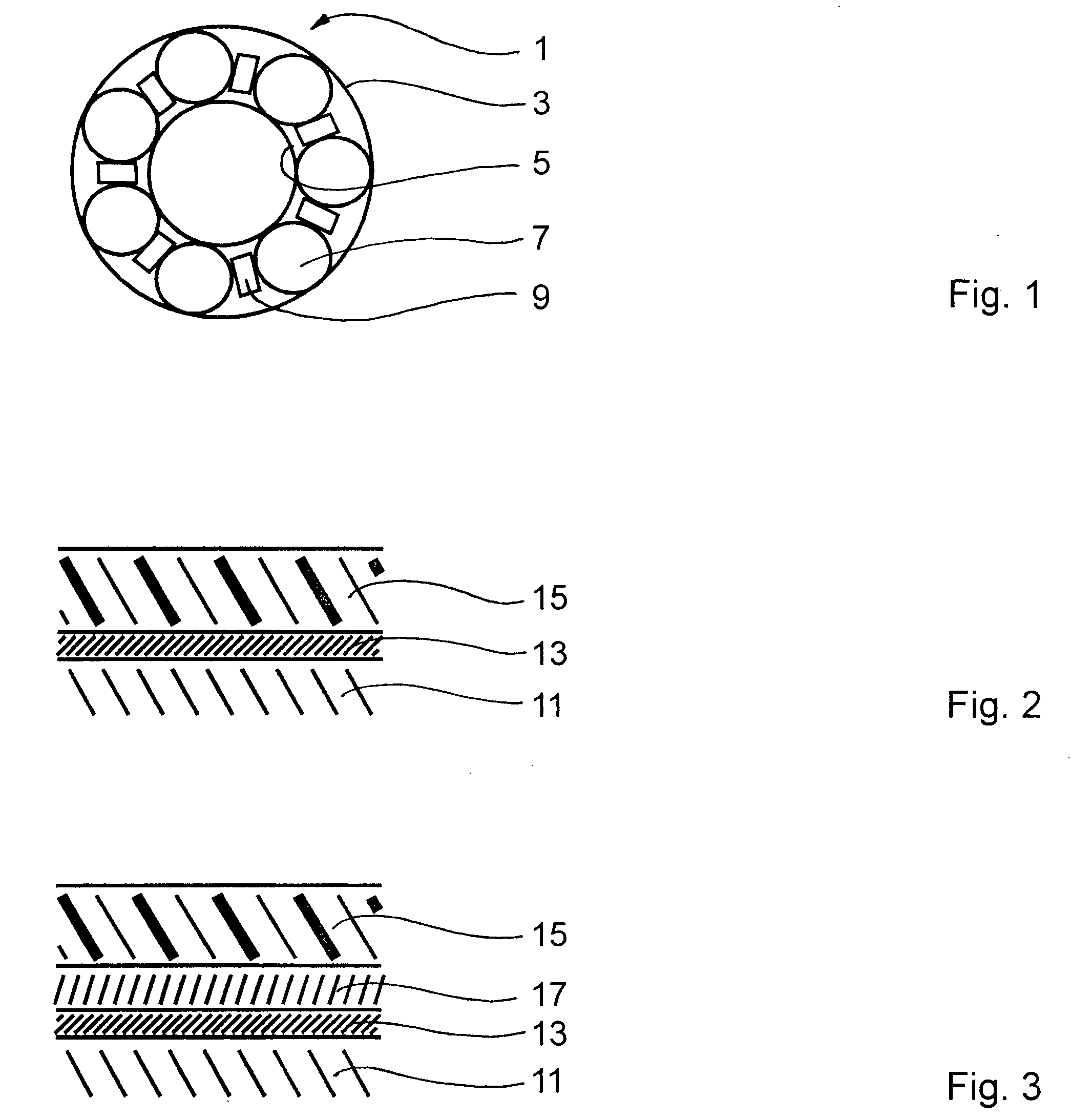
[0006] A very thin formation of the polyimide coating is simpler and more cost-favorable to produce, and increases the advantages of hydrolytic stability and longer service life. As protection against corrosion of the carrier material that normally consists for the most part of iron, a passivation coating is applied to the carrier material below the polyimide coating, i.e., chronologically before applying the latter. To the extent that high pressure loads are to be expected in the bearing assembly, a pressure-resistant coating may be additionally applied to the passivated carrier material below and / or inside the polyimide coating.

Problems solved by technology

For special applications, which are expected to function as much as possible without a lubricant, the ball bearing may also include very expensive bearing elements of a ceramic material, of steel coated with carbide in a vacuum, or a solid material of plastic.

Method used


Image

  • Bearing or drive assembly with coated elements
  • Bearing or drive assembly with coated elements

Examples


Embodiment Construction

[0012] The present invention now will be described more fully hereinafter with reference to the accompanying drawings, in which some, but not all embodiments of the invention are shown. Indeed, the invention may be embodied in many different forms and should not be construed as limited to the embodiments set forth herein; rather, these embodiments are provided so that this disclosure will satisfy applicable legal requirements. Like numbers refer to like elements throughout.

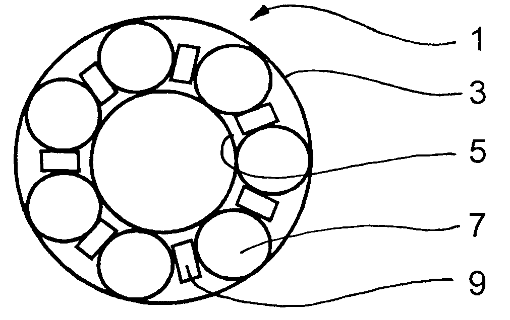
[0013] In the first embodiment, a bearing assembly 1 is constructed as a ball bearing. Between an outer ring 3 with a larger diameter and an inner ring 5 with a smaller diameter, a plurality of balls 7 are arranged, which are kept in spaced relationship by a ball cage 9. In known manner, the balls 7 abut an inside wall of the outer ring 3 and an outside wall of the inner ring 5. The inside wall of the outer ring 3, the outside wall of the inner ring 5, and preferably also the balls 7 are coated by the following m...


PUM

PropertyMeasurementUnit
thicknessaaaaaaaaaa
dimensionaaaaaaaaaa
pressure-aaaaaaaaaa

Abstract

In a bearing assembly or a gearing with a least two bearing elements or gearing elements that are adapted for movement relative to each other, at least one bearing element or gearing element comprises a polyimide coating on a carrier material.

Description

BACKGROUND OF THE INVENTION [0001] The present invention relates to a bearing or drive assembly with at least two bearing elements or drive elements that are adapted for movement relative to each other. [0002] As a known bearing assembly of the above-described type, a ball bearing comprises a plurality of steel balls that are positioned between an inner ring and an outer ring, and the balls are kept in spaced relationship by a cage. A lubricant reduces friction and wear in the ball bearing and simultaneously protects the bearing elements against corrosion. For special applications, which are expected to function as much as possible without a lubricant, the ball bearing may also include very expensive bearing elements of a ceramic material, of steel coated with carbide in a vacuum, or a solid material of plastic. BRIEF SUMMARY OF THE INVENTION [0003] One aspect of the present invention is the provision of improvements to a bearing or drive assembly of the type described above. In acc...

Claims


Application Information

Patent Timeline
Patent Type & Authority Applications(United States)
IPC IPC(8): F16C19/20F16C33/30F16C33/32F16C33/62
CPCF16C33/32F16C33/62F16C33/64F16C33/201Y10S384/909F16C2208/40
Inventor GORLACH, BERND
Owner GORLACH BERND
Learn More