Front-loadable refuse container having side-loading robotic arm with motors and other mass mounted at rear of container and use of same with front-loading waste-hauling vehicle having hydraulic front forks or other retractably engageable lift means

a technology of front-loading and waste cans, which is applied in the direction of refuse collection, transportation items, packaging goods, etc., can solve the problems of manual fetching, lifting and/or returning of waste cans, and affecting the safety of drivers

Active Publication Date: 2005-05-05
CUROTTO JOHN M
View PDF13 Cites 53 Cited by
  • Summary
  • Abstract
  • Description
  • Claims
  • Application Information

AI Technical Summary

Benefits of technology

[0025] A method for configuring a combination of an intermediate container and a waste-fetching robotic arm in accordance with the disclosure comprises: (a) positioning a major portion of the mass of a robotic arm mechanism behind a rear, refuse-containing wall of the intermediate container; (b) attaching fork pockets to side walls of the container for receiving forks of a front-loading vehicle, where the fork pockets extend or are extendibl

Problems solved by technology

It is not uncommon in the haste of trying to do the job quickly, for an operator to misjudge the position of an upwardly-rising bin and to prematurely initiate a fork titling motion during the execution of an over-the-top dumping operation.
Such a premature tilt may cause the refuse bin to miss its intended target, namely, an opening at the top of the rear-mounted hopper (a hopper that rides behind the operator's cab) and instead to tilt and crash into an upper front portion of the truck (e.g., the cab roof).
Such manual fetching, hauling, lifting and/or return of waste cans tends to be exhausting and time consuming.
One drawback of this type of curb-side cart dumper is that the vehicle driver still has to step out from the driver's cab, fetch the waste can, and manually attach the can (or curb-side waste-cart as it may be called) to the integrated cart dumper prior to receiving powered assistance from the integrated cart dumper.
Another drawback of this type of integrated curb-side cart dum

Method used


Image

  • Front-loadable refuse container having side-loading robotic arm with motors and other mass mounted at rear of container and use of same with front-loading waste-hauling vehicle having hydraulic front forks or other retractably engageable lift means
  • Front-loadable refuse container having side-loading robotic arm with motors and other mass mounted at rear of container and use of same with front-loading waste-hauling vehicle having hydraulic front forks or other retractably engageable lift means
  • Front-loadable refuse container having side-loading robotic arm with motors and other mass mounted at rear of container and use of same with front-loading waste-hauling vehicle having hydraulic front forks or other retractably engageable lift means

Examples


embodiment 300

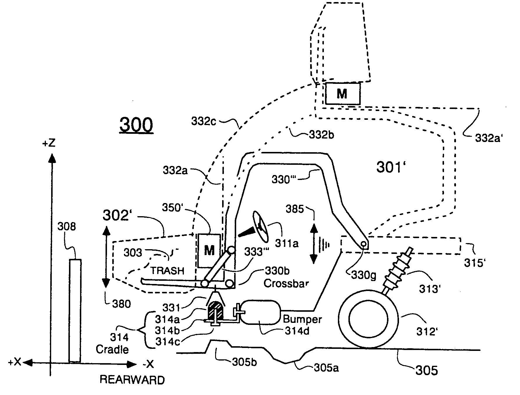
[0074] Other cooperating shapes may be used for the combination of the bumper-engaging coupling 331 and the elastomeric projection 314a besides bell and dome. For example, the bumper bracket 314b could be cup shaped and lined on its interior with elastomeric material while the bumper-engaging coupling 331 could instead be ball-shaped to fit into and ride inside the elastomerically-lined cup. The order of where the elastomeric material resides and where the bumper-engaging coupling resides can be reversed or other wise rearranged. For example, the elastomeric material may instead ride in bell 331 while projection 314a becomes a metal ball to fit ball-in-socket fashion into the elastomerically-lined bell (331). Elastomeric material may be provided both in the portion that rides on the vehicle bumper 314d and the portion of the cradle mechanism which moves with the forks. The end result is that stresses and strains from various shakings of the robotic arm mechanism 350′ can be absorbed...

embodiment 400

[0097] Each outer pocket member 405 may include an angled portion 405a that aligns with a similarly angled chamfer 407 in the bottom curbside and streetside edges of the container 402″. A similarly angled surface may be provided on each of the reinforcement extension members 402e″ (only one shown) of the container. The angled outer surface 405a of each outer pocket member 405 may be welded, bolted, and / or otherwise fastened to the correspondingly angled walls of the main container and of the re-enforcement extension members 402e″. The inside-located ends of the reinforcement extension members 402e″ (the ends near the crossbar) may also function as bumper pads. Although a fork-based embodiment 400″ has been detailed in FIG. 4B, it is within the contemplation of the disclosure that elastomeric damping means may be integrally incorporated into embodiments which allow for other retractably engageable lift means. For example, if the A-frame approach is implemented, the elastomeric dampin...

embodiment 500

[0102]FIGS. 5A-5B respectively show top and side schematic views of another embodiment 500. Where practical like reference numbers in the “500” century series are used for elements of FIGS. 5A-5B that have counterpart elements in the “300” century series in FIGS. 3A-3B. It may be readily seen that there are two robotic arms 351′ and 551 in FIG. 5A. The back-mounted arm may be essentially the same as in the previous figures and may have most or all of its motor mass mounted in rear portion 350′. The front-mounted arm 551 is arranged to pick up waste items (e.g., 509c) disposed on the opposed, left side of the intermediate container at the same time that arm 351′ picks up waste items (e.g., 509b) disposed on the right side. The front-mounted arm mechanism 550 is not a full mirror image of the back-mounted portion 350′. Instead, a substantial portion of the motor mass and controls mass for the front-mounted arm 550 resides in the back-mounted portion 350′. Low-mass, power transferring ...


PUM

PropertyMeasurementUnit
Lengthaaaaaaaaaa
Massaaaaaaaaaa
Mechanical propertiesaaaaaaaaaa

Abstract

A front-loading, refuse collecting vehicle is modularly provided with a combination of a low-profile, front-loadable waste bin (intermediate container) and one or more, side-loading robotic arms. To reduce mechanical stresses along couplings between the vehicle and the combination of the intermediate container and the robotic arm(s), a major portion of the mass of the robotic arm mechanism is situated to the rear of the intermediate container so that a mass and beam combination is defined where the mass-supporting beam has reduced length. More specifically, hydraulic and/or other relatively massive motor means of the robotic arm mechanism are mounted to the rear of a refuse-containing wall of the intermediate container. Elastomeric and/or other dampening means may be interposed between the vehicle and the bulk mass of the combination of the intermediate container and robotic arm mechanism for converting into heat some of the vibrational energy which may otherwise move between the vehicle and the combination of the intermediate container and robotic arm mechanism. A modular sled system may be provided for supporting different robotic arms in combination with refuse containers made of different materials as may be appropriate for different waste collection situations.

Description

1. FIELD OF DISCLOSURE [0001] The present disclosure of invention relates generally to commercial-scale collection and hauling of refuse in residential and industrial settings. [0002] The disclosure relates more specifically to so-called intermediate containers which can be transported by a vehicle and can receive collected refuse intermediate to the refuse being dumped into a larger refuse-containing hopper of the transport vehicle. [0003] The disclosure relates yet more specifically to the positioning of, and / or mounting of, motor-driven (e.g., hydraulically-actuated) collection-assisting devices such as robotic arms, relative to the positioning of a refuse container (e.g., an intermediate container) which can be engaged and lifted by a retractably engageable lift means such as a fork-lift, particularly when the combination of container and motor-driven collection-assisting device(s) is lifted by forks or other retractably engageable lift means provided on a steered transportation...

Claims


Application Information

Patent Timeline
IPC IPC(8): B65FB65F1/12B65F3/02B65F3/04
CPCB65F1/122B65F3/041B65F3/046Y10T29/49826B65F2003/0269B65F2003/0279B65F1/10B65F2003/023B65F2003/0276
Inventor CUROTTO, JOHN M.SUDEN, EDWARD M.GIMLAN, GIDEON
Owner CUROTTO JOHN M
Why Eureka
Try Eureka