Centrifugal compressor surge detection using a bi-directional MFM in a fuel cell system

a fuel cell and surge detection technology, applied in the direction of machines/engines, electrical generators, mechanical equipment, etc., can solve the problem of relatively high manufacturing cost of meas

Inactive Publication Date: 2005-05-05
GM GLOBAL TECH OPERATIONS LLC
View PDF1 Cites 23 Cited by
  • Summary
  • Abstract
  • Description
  • Claims
  • Application Information

AI Technical Summary

Problems solved by technology

MEAs are relatively expensive to manufacture and require certain conditions for effective operation.

Method used


Image

  • Centrifugal compressor surge detection using a bi-directional MFM in a fuel cell system

Examples


Embodiment Construction

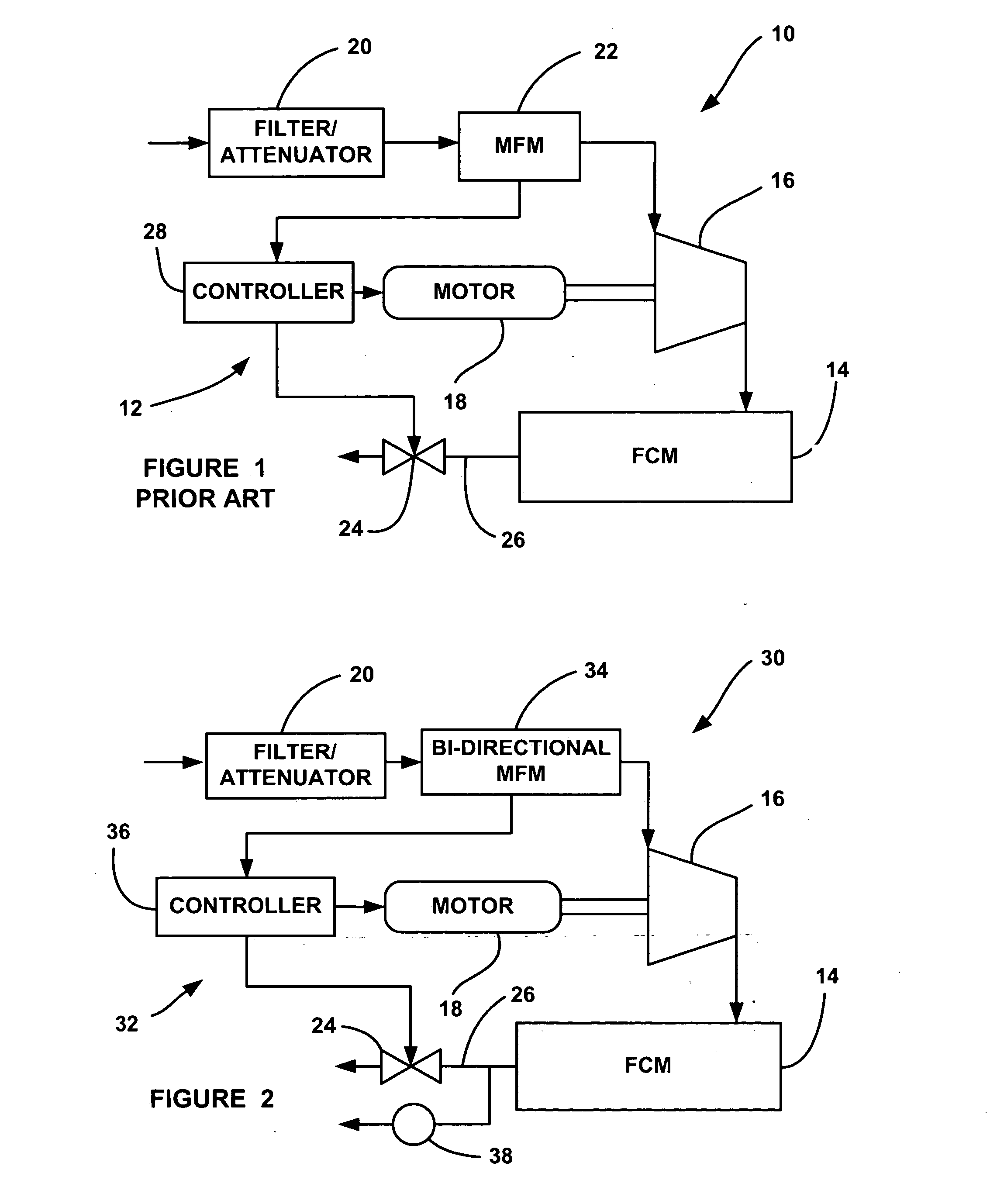
[0016] The following description of the embodiments of the invention directed to a fuel cell system including a bi-directional mass flow meter that provides compressor surge detection is merely exemplary in nature, and is in no way intended to limit the invention or its applications or uses.

[0017]FIG. 2 is a plan view of a fuel cell system 30 including an air delivery sub-system 32, according to an embodiment of the present invention. The system 30 is similar to the system 10 discussed above, where like reference numerals identify like elements. In this design, the air delivery sub-system 32 includes a bi-directional MFM 34 that measures airflow through the centrifugal compressor 16 in both directions. Because the MFM 34 is capable of detecting airflow in both directions, it acts as a surge protection device to detect backpressure to the compressor 16 from the FCM 14. In one embodiment, the MFM 34 is a known bidirectional MFM sometimes used in small four cylinder gas engines to mea...


PUM

PropertyMeasurementUnit
speedaaaaaaaaaa
pressureaaaaaaaaaa
mass flow meteraaaaaaaaaa

Abstract

A fuel cell system including a turbomachine compressor that delivers charge air to the cathode side of a fuel cell module. A bidirectional mass flow meter measures the airflow through the compressor, and provides an indication of a reverse airflow through the compressor for surge protection. A controller receives a signal from the mass flow meter indicative of the reverse flow. The controller controls a motor driving the compressor and a back pressure valve at the cathode exhaust of the fuel cell module to control the pressure in the fuel cell module to remove the surge condition.

Description

BACKGROUND OF THE INVENTION [0001] 1. Field of the Invention [0002] This invention relates generally to an air delivery sub-system for a fuel cell system and, more particularly, to an air delivery sub-system for a fuel cell system, where the air delivery sub-system includes a bidirectional mass flow meter (MFM) that measures airflow to and from a turbomachine type compressor in the sub-system to detect compressor surges. [0003] 2. Discussion of the Related Art [0004] Hydrogen is a very attractive fuel because it is clean and can be used to efficiently produce electricity in a fuel cell. The automotive industry expends significant resources in the development of hydrogen fuel cells as a source of power for vehicles. Such vehicles would be more efficient and generate fewer emissions than today's vehicles employing internal combustion engines. [0005] A hydrogen fuel cell is an electrochemical device that includes an anode and a cathode with an electrolyte therebetween. The anode receiv...

Claims


Application Information

Patent Timeline
Patent Type & Authority Applications(United States)
IPC IPC(8): H01M8/04
CPCF04D27/001F04D27/0207Y02E60/50H01M8/04089F04D27/0261Y02B30/70
Inventor RAINVILLE, JOSEPH D.
Owner GM GLOBAL TECH OPERATIONS LLC
Why Eureka
Try Eureka