Minimally invasive surgery device

a surgery device and minimally invasive technology, applied in the field of endoscopic surgical instruments, can solve the problems of not being completely satisfactory to surgeons, various tools designed, and working in small places that are not visible to the naked eye,

Inactive Publication Date: 2005-05-05
STELZER PAUL +1
View PDF27 Cites 130 Cited by
  • Summary
  • Abstract
  • Description
  • Claims
  • Application Information

AI Technical Summary

Benefits of technology

[0019] To achieve these advantageous features of the present invention, there is provided an instrument comprising a node at the distal end of a shaft, wherein a surgical tool can be inserted through the node and the node can be rotated allowing manipulation and orientation of the surgical tool at the distal end of the shaft through control remote from the distal end of the shaft. Further, there is provided a particular node structure at the distal end of the device which, through control remote from the distal end of the device, can rotate a surgical tool in the (X) and (Y) dimensions, and allows for the movement of the tool in the (Z) dimension. There further is provided at least two cameras configured such that at the appropriate distance from the device, the surgical area will appear to the operator in stereoscopic vision. There is also provided an instrument comprising (i) a node at the distal end of a shaft, wherein a tool can be inserted through the node allowing manipulation and orientation of the tool at the distal end of the shaft through control remote from the distal end of the shaft, (ii) a plurality of cameras located at the distal end of the shaft positioned so that they can convey a stereoscopic image to an operator; and (iii) a light source.

Problems solved by technology

As these techniques have been developed, workers and surgeons have been faced with the problem of working in small places not visible by direct line of sight.
Various tools have been designed to deal with this problem although none has been entirely satisfactory.
This device, however, would allow only circular rotation of the tool, and does not allow for manipulation and orientation of the tool at the distal end of the shaft.
The above devices have been problematic because the visual contact with the surgery location has been inadequate, further compounded by difficulties in the manipulation and orientation of the tools.
Moreover, the use of a single camera has resulted in a lack of depth perception.
This results in decrease of blood flow through the vessel and subsequent ischemia (lack of oxygen) in the tissues served by this vessel.
The aorta itself can also be severely affected in some patients.
The hazard of embolization of atherosclerotic debris downstream in the treated vessel raises the risk of serious injury to the very structures one is trying to protect.
The drawbacks to this process are that the patient is usually under general anesthesia, major trauma can be caused by the substantial body opening, only a limited portion of a limited number of arteries can be reached by direct incision, and the surgeon is unable to see the distal area where the plaque breaks.
Neither of these devices is of any use in a totally occluded vessel.

Method used


Image

  • Minimally invasive surgery device
  • Minimally invasive surgery device
  • Minimally invasive surgery device

Examples


Embodiment Construction

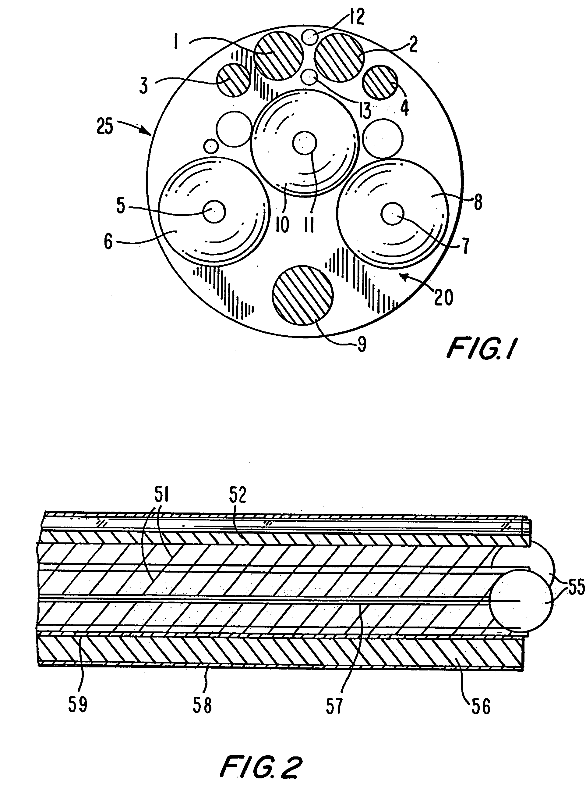
[0040]FIG. 1 shows an end view of the configuration of one of the preferred embodiments. RGB chip camera units 1 and 2 are positioned to the right and left of the center axis of the shaft, and are spaced such that the targeted area will be within the focal distance of the cameras so that a stereoscopic image of the surgical area can be produced. Light is provided by fiber optic sources 3 and 4. Three nodes (6, 8 and 10) are located below the cameras, and each node has a tool port at its center (5, 7 and 11). A balloon port (9) may optionally be used. Sources for H2O and CO2 are shown at 12 and 13. The selection of the number of tools, nodes, ports and other mechanisms may vary depending on the nature of the surgery to be performed.

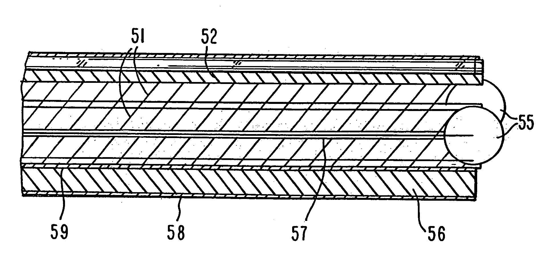
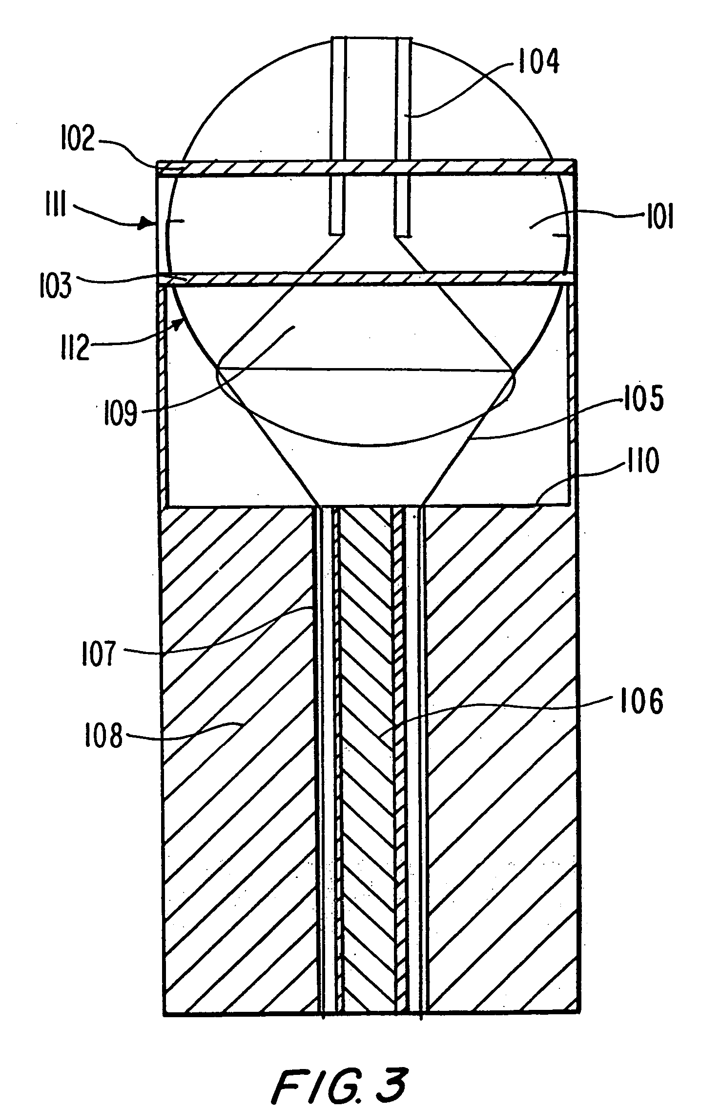
[0041] A protective plate, 20, is placed over the distal end of the catheter, 25, with openings for all desired ports and nodes. The plate is fastened to the outer surface of the catheter, and provides both support for the distal end of the various ports ...


PUM


Abstract

Provided is a surgical instrument comprising a node rotatably mounted within a restraining structure at the distal end of a shaft, The node can be rotated allowing manipulation and orientation of a surgical tool extending from the node at the distal end of the shaft through control remote from the distal end of the shaft. Cameras may also be located at the distal end of the shaft allowing stereoscopic imaging to be conveyed to an operator. The surgical instrument is well suited for administering biologically active substances to a desired location. The method of administration comprises insertion of a flexible shaft comprising a channel, controlling the location of the distal end of the shaft through control cables within the shaft, and projecting the biologically active substance from the end of the channel at the desired location.

Description

RELATED APPLICATIONS [0001] This application is a continuation-in-part of allowed U.S. application Ser. No. 08 / 916,147 filed Aug. 21, 1997, which is incorporated herein by reference. All public documents referred to herein are likewise incorporated by reference.FIELD OF THE INVENTION [0002] The present invention relates to the field of minimally invasive or endoscopic surgical instruments, and more particularly, to an endoscopic instrument designed to allow improved instrument control and orientation, and to allow improved visual contact with the surgical area. BACKGROUND OF THE INVENTION [0003] Minimally invasive surgery techniques have become increasingly popular due to the rapid healing and greater efficiency provided by such techniques. As these techniques have been developed, workers and surgeons have been faced with the problem of working in small places not visible by direct line of sight. Various tools have been designed to deal with this problem although none has been entir...

Claims


Application Information

Patent Timeline
Patent Type & Authority Applications(United States)
IPC IPC(8): A61B1/00A61B1/018A61B1/04A61B1/05A61B1/06A61B17/00A61B17/28A61B19/00
CPCA61B1/00098A61B1/00193A61B1/018A61B2019/5227A61B17/00234A61B2017/2927A61B1/05A61B2090/371
Inventor STELZER, PAULSTELZER, STUART
Owner STELZER PAUL
Why Eureka
Try Eureka