Patient lifting apparatus

a technology for lifting equipment and patients, applied in hospital equipment, medical science, nursing beds, etc., can solve the problems of difficult installation of devices, difficult movement or transfer from patients' beds, and requiring relatively heavy materials to provide structural strength, etc., to achieve convenient operation, simple mechanical operation, and reliable and safe operation.

Inactive Publication Date: 2005-05-12
HAWK MOBILITY SYST
View PDF17 Cites 25 Cited by
  • Summary
  • Abstract
  • Description
  • Claims
  • Application Information

AI Technical Summary

Benefits of technology

[0011] It is a further object of the present invention to provide a patient lifting apparatus that is relatively simple mechanically while at the same time being reliable and safe in operation.
[0012] It is a further object of the present inve

Problems solved by technology

Persons confined to a bed due to illness, age, obesity and so forth often have such limited mobility that movement or transfer from their bed is extremely difficult.
However, the support brackets make these devices difficult to install in many locations where a permanent installation is undesirable (e.g., a temporary home care situation).

Method used


Image

  • Patient lifting apparatus
  • Patient lifting apparatus
  • Patient lifting apparatus

Examples


Embodiment Construction

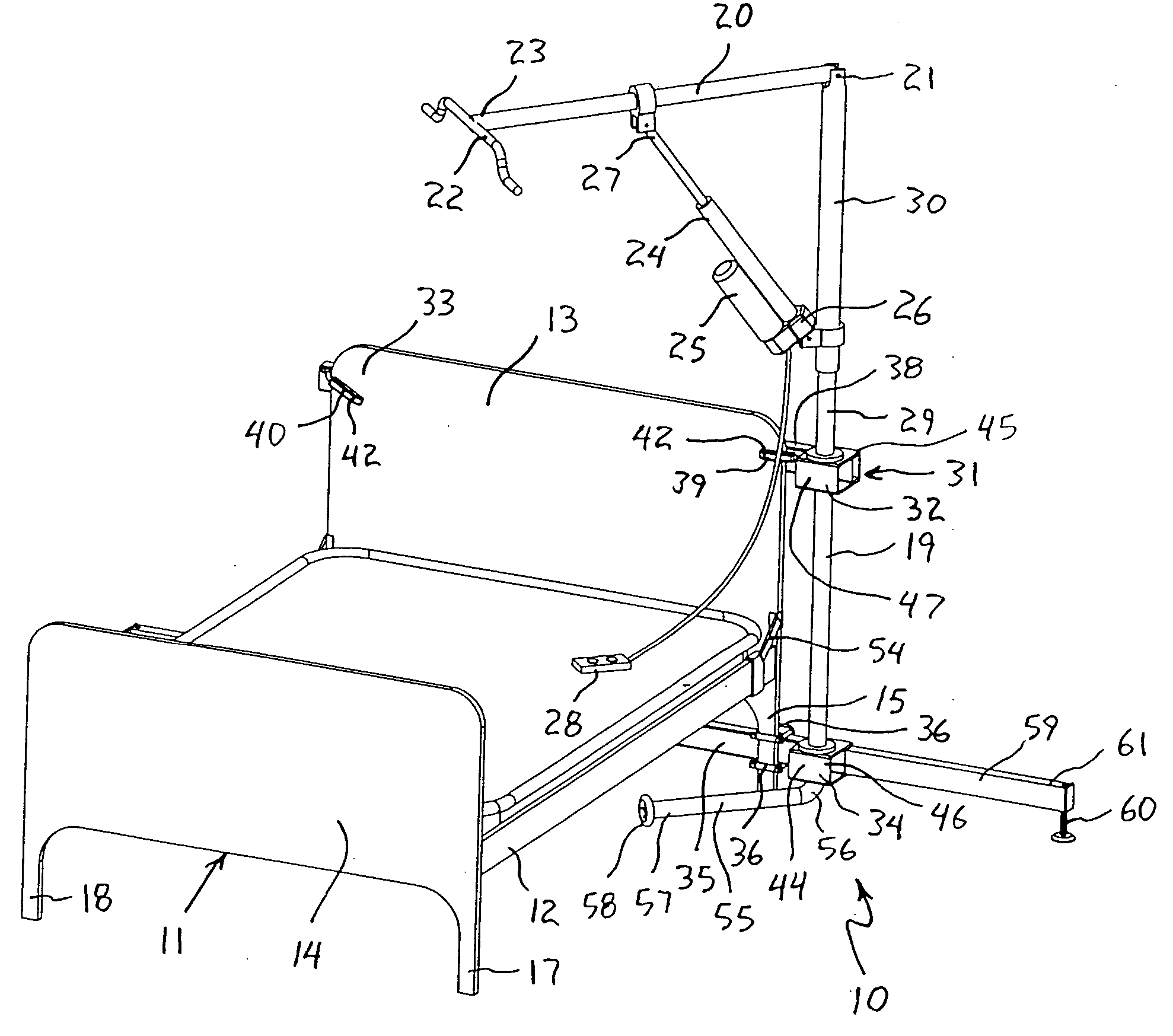
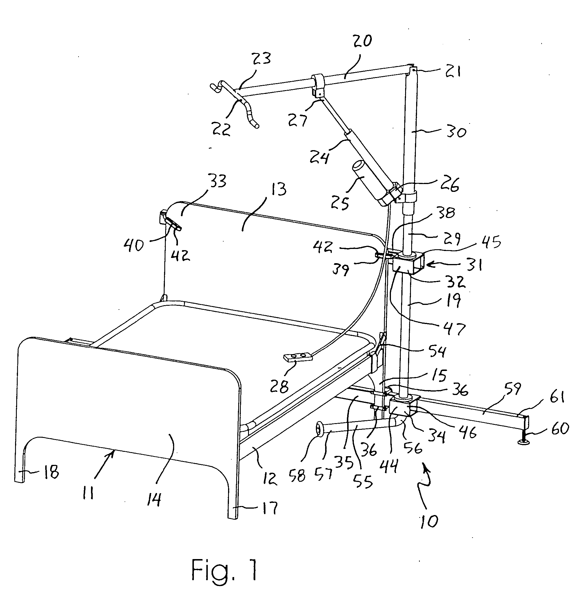
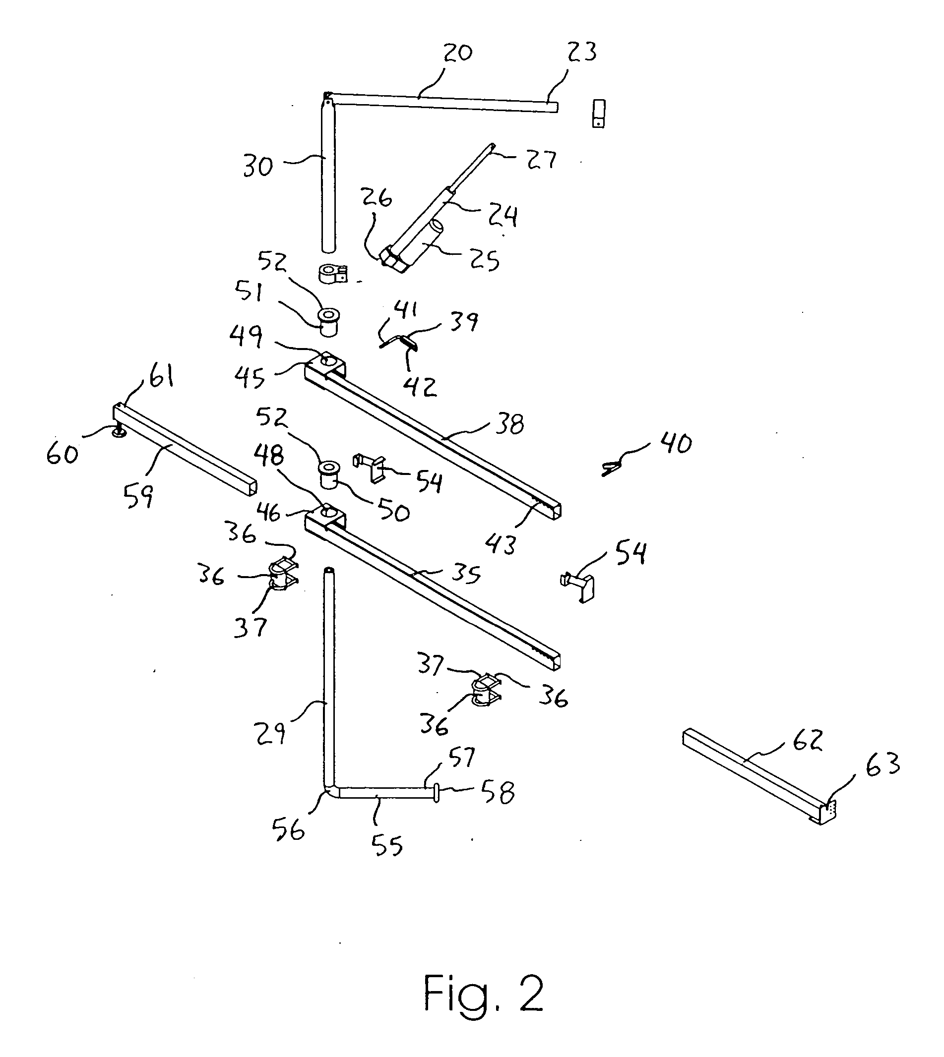
[0029] A patient lifting apparatus according to preferred embodiments of the present invention will now be described in detail with reference to FIGS. 1 to 8b of the drawings.

[0030] The patient lifting apparatus 10 according to a first embodiment is shown in FIG. 1 in combination with a bed frame 11, and is shown in FIG. 2 as an exploded view of the various individual components. The bed frame 11 is a conventional design including left and right side rails 12, a headboard 13, and a footboard 14. A first pair of legs 15, 16 are formed at the bottom of the headboard 13, and a second pair of legs 17, 18 are formed at the bottom of the footboard 14. A plurality of cross members (not shown) normally extend between the side rails 12 to support a box spring and mattress assembly (not shown) in the case of most beds found in private homes, or a platform and folding mechanism (not shown) in the case of adjustable hospital beds.

[0031] Although little standardization exists in bed frames, st...


PUM


Abstract

A patient lifting apparatus is provided that attaches to a bed frame having a plurality of legs and a headboard. The apparatus includes an upright member, a boom mechanically associated with the upright member, an upper support bar that extends across the bed frame and secures the upright member to each side of the headboard, and a lower support bar that extends across the bed frame and secures the upright member to the legs. The upright member is supported for rotation about a vertical axis by upper and lower bearings on the upper and lower support bars, respectively. A telescoping foot member extends from the lower support bar and is movable between a stored position and an extended position for stabilizing the lifting apparatus. A support arm extends from a lower end of the upright member and rotates along with the upright member to transfer vertical forces into the floor.

Description

BACKGROUND OF THE INVENTION [0001] 1. Field of the Invention [0002] The present invention relates generally to patient lifting equipment. In particular, the present invention relates to a patient lifting apparatus for lifting and transferring incapacitated persons to and from a bed. [0003] 2. Description of the Related Art [0004] Persons confined to a bed due to illness, age, obesity and so forth often have such limited mobility that movement or transfer from their bed is extremely difficult. It is well known to provide such persons with a patient lift to hoist the person from the bed and move him or her into a wheel chair or other desired location. Most such prior art patient lifts permit the patient to be raised or lowered and also permit the patient to be swiveled away from the bed about a vertical support member. [0005] For example, in U.S. Pat. Nos. 4,554,691 and 5,459,891, patient lifting devices are disclosed in which a vertical support member is attached to support brackets ...

Claims


Application Information

Patent Timeline
IPC IPC(8): A61G7/05A61G7/08A61G7/10
CPCA61G7/05A61G7/1017A61G7/1076A61G7/1061A61G7/1067A61G7/1044
Inventor HAWK, GARY LEEHAWK, LINDA L.KING, CALEOB
Owner HAWK MOBILITY SYST
Why Eureka
Try Eureka