Knocking determination apparatus for internal combustion engine

a technology for internal combustion engines and determination apparatuses, which is applied in the direction of machines/engines, electric control, instruments, etc., can solve the problems of low reliability of internal combustion engines having such two types of injectors in the determination of knocking, and achieve the effect of preventing knocking in internal combustion engines

Inactive Publication Date: 2005-05-12
TOYOTA JIDOSHA KK
View PDF5 Cites 53 Cited by
  • Summary
  • Abstract
  • Description
  • Claims
  • Application Information

AI Technical Summary

Benefits of technology

[0011] A further aspect of the present invention is a method for preventing knocking in an internal combustion engine. The internal combustion engine includes a first injector for directly injecting fuel into a combustion chamber, a second injector for injecting fuel into an intake system, and a spark plug. The method includes measuring vibration of the internal combustion engine to generate a detection signal representing the vibration, adjusting a knock determination period in accordance with the ratio between the amount of fuel the first injector

Problems solved by technology

Therefore, an internal combustion engine having such two types of inje

Method used


Image

  • Knocking determination apparatus for internal combustion engine
  • Knocking determination apparatus for internal combustion engine
  • Knocking determination apparatus for internal combustion engine

Examples


first embodiment

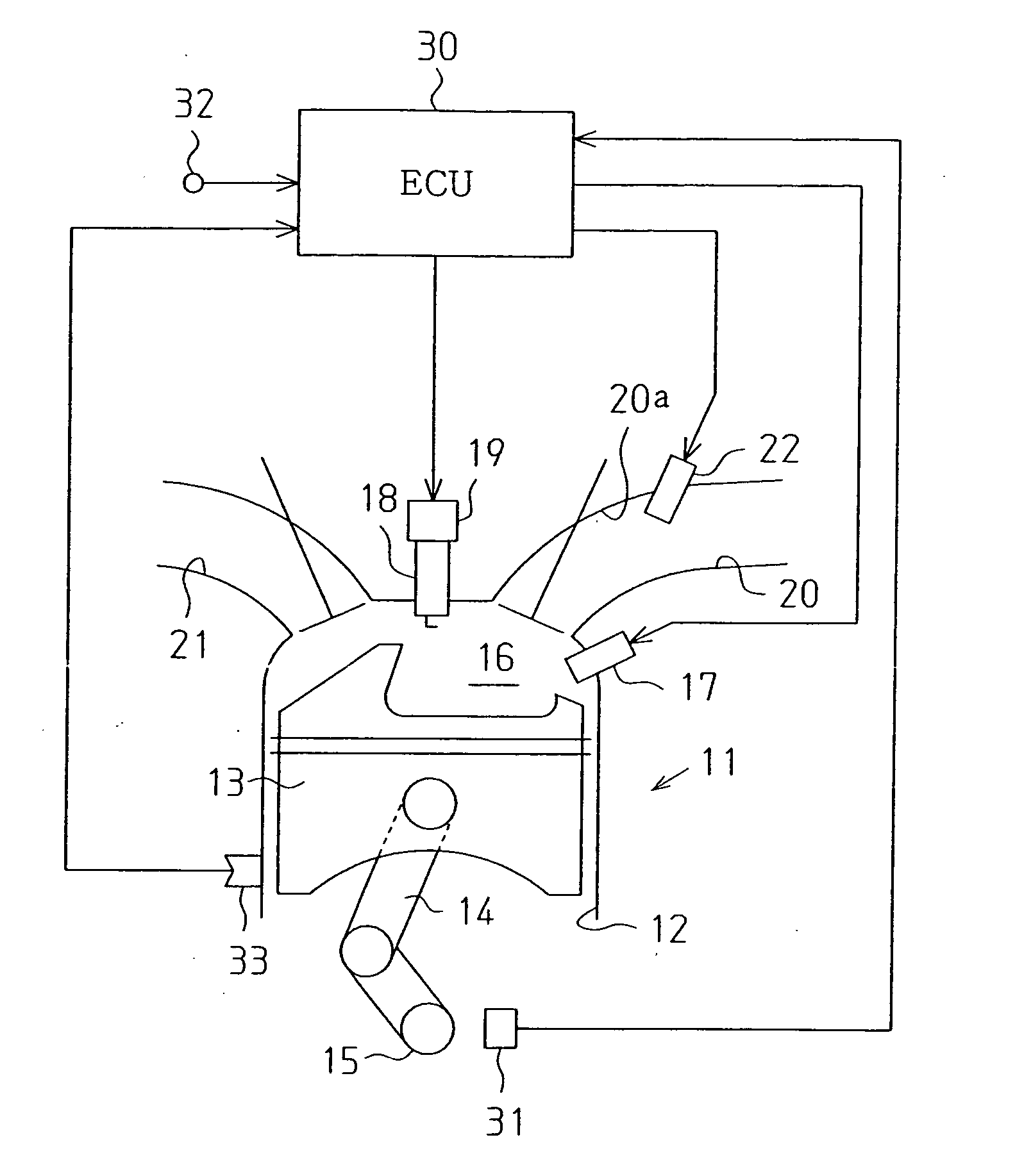
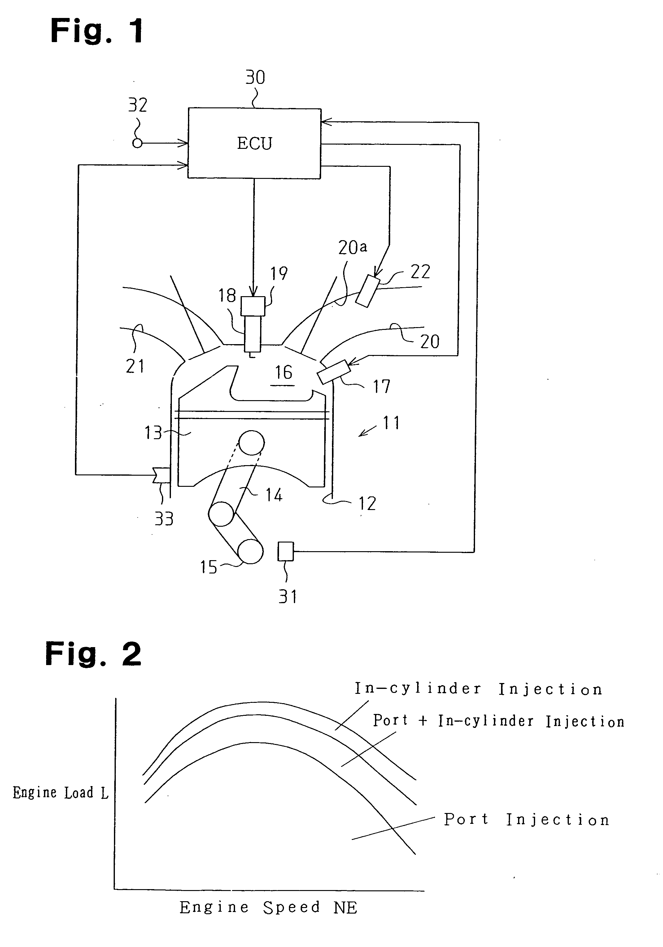
[0028] A knocking determination apparatus applied to an internal combustion engine according to the present invention will now be described.

[0029]FIG. 1 schematically shows an internal combustion engine 11. The internal combustion engine 11 is a four-cycle internal combustion engine having a plurality of cylinders 12 (only one shown in FIG. 1). A piston 13 reciprocates in each of the cylinders 12. The piston 13 is linked to a crankshaft 15, which functions as an output shaft for the internal combustion engine 11, by a connecting rod 14. The connecting rod 14 converts reciprocation of the piston 13 to rotation of the crankshaft 15.

[0030] A combustion chamber 16 is defined above the piston 13 in each of the cylinders 12. An injector (in-cylinder injector 17) is attached to each cylinder 12 to directly inject fuel into the associated combustion chamber 16. The in-cylinder injector 17 is supplied with high-pressure fuel by a fuel supply mechanism (not shown). Fuel is directly supplied ...

second embodiment

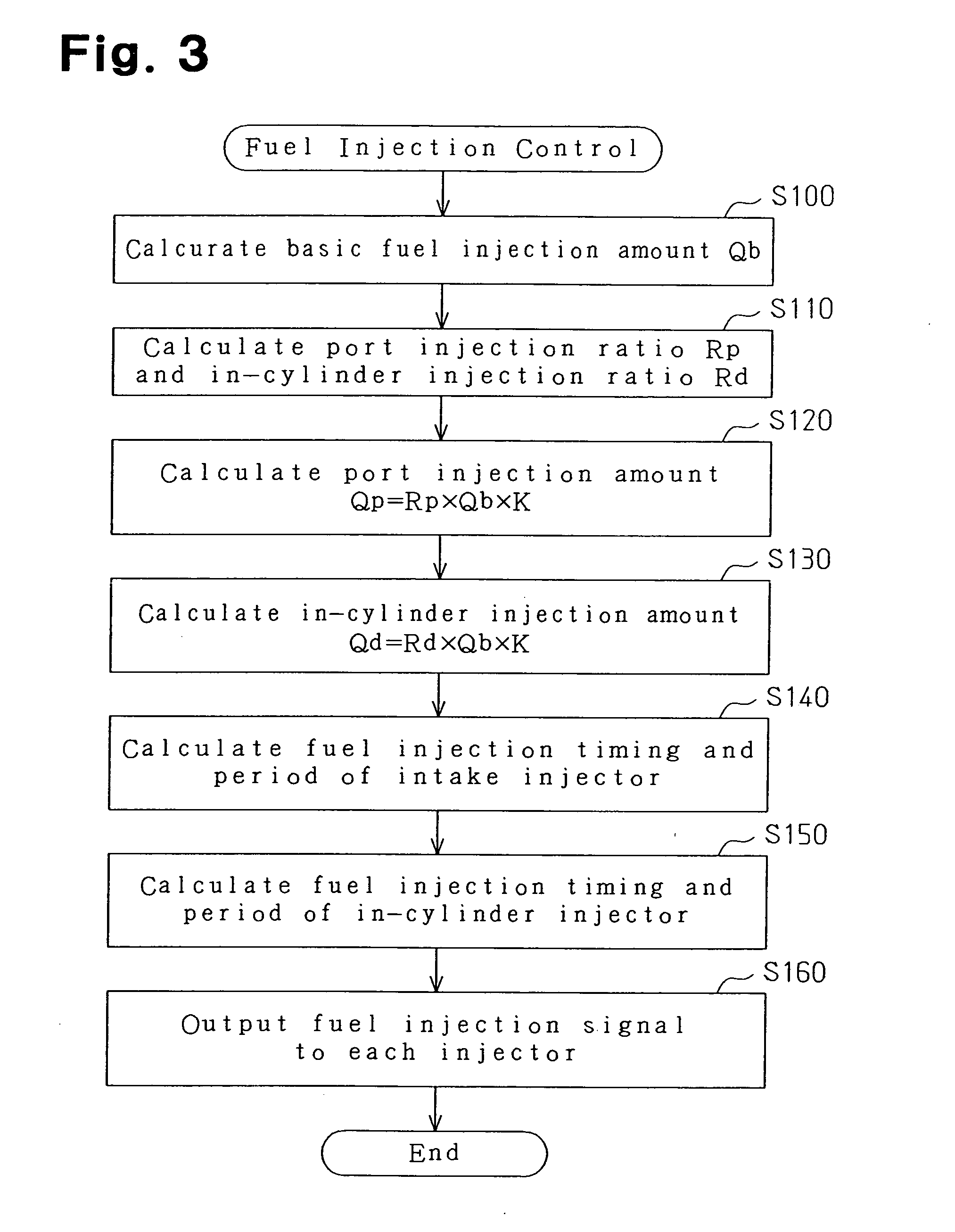
[0097] In the second embodiment, the inactivation timing of the gate signal is set such that the second knock determination period Tkdd ends earlier than the start of fuel injection from the in-cylinder injector 17, that is, such that the second knock determination period Tkdd ends at a timing advanced from the timing at which the in-cylinder injector 17 starts fuel injection. The timing at which the in-cylinder injector 17 starts fuel injection is calculated by the process of step S150 in the fuel injection control (FIG. 3) as described above. The inactivation timing of the gate signal is more advanced than the fuel injection start timing. The operational noise is not mixed in the output signal from knock sensor immediately after the fuel injection signal is activated when starting fuel injection and there is a response delay time RTS. The response delay time RTS corresponds to the time until the nozzle needle abuts against the stopper and the time the vibrations generated by the a...

third embodiment

[0109] Thus, the third embodiment has the following advantage in addition to advantages (1) and (2).

[0110] (4) The knock determination is not affected by the noise generated by operation of the in-cylinder injector 17. This prevents erroneous determination that would be caused by vibrations generated by the operation of the in-cylinder injector 17.

[0111] Next, a knocking determination apparatus according to a fourth embodiment of the present invention will be described focusing on the different features from the first embodiment.

[0112] In the first embodiment, reliability of the knocking determination result is ensured by setting the knock determination period while taking into account the change in the knock initiation timing caused by alteration of the ratio of fuel injected by the in-cylinder injector 17.

[0113] Apart from this, as the combustion rate increases by altering the ratio of fuel injected from in-cylinder injector 17, the vibrations generated along with the combustio...


PUM


Abstract

An electronic control for determining knocking in an internal combustion engine having an intake injector for injecting fuel into an air intake port and an in-cylinder injector for directly injecting fuel into a combustion chamber. Knocking is determined based on an output signal from a knock sensor during a knock determination period. The electronic control unit alters the knock determination period in accordance with the ratio of the amount of fuel injected by the two injectors.

Description

CROSS-REFERENCE TO RELATED APPLICATIONS [0001] This application is based upon and claims the benefit of priority from prior Japanese-Patent Application No. 2003-382842, filed on Nov. 12, 2003, the entire contents of which are incorporated herein by reference. BACKGROUND OF THE INVENTION [0002] The present invention relates to a knocking determination apparatus for an internal combustion engine having an intake injector for injecting fuel into an intake system and an in-cylinder injector for injecting fuel into a combustion chamber. [0003] An internal combustion engine having two different types of injectors for separately injecting fuel into an intake system, such as an air intake port, and a combustion chamber is known in the prior art (refer to Japanese Laid-Open Patent Publication 7-103048). [0004] This type of internal combustion engine improves fuel consumption and ensures appropriate engine output by switching fuel injection modes with the two types of injectors in accordance ...

Claims


Application Information

Patent Timeline
IPC IPC(8): F02D35/02F02D41/22F02D45/00F02M69/04F02P5/152G01L23/22
CPCF02D35/027F02D41/3094F02D2250/14Y02T10/46F02P5/152G01L23/225F02M69/046Y02T10/40F02D45/00F02D41/22
Inventor OHTANI, MOTOKI
Owner TOYOTA JIDOSHA KK
Why Eureka
Try Eureka