Face masks

Inactive Publication Date: 2005-05-12
SMITHS GRP PLC
View PDF8 Cites 183 Cited by
  • Summary
  • Abstract
  • Description
  • Claims
  • Application Information

AI Technical Summary

Benefits of technology

[0005] The peripheral sealing edge of the canopy preferably is tapered to a reduced thickness and an increased flexibility at its edge. The gas port is preferably provided on the reinforcement member. The gas port may have a connector projecting therefrom for connection to a gas supply tube, the port being located in line with the mouth of the patient and the connector being angled such that it projects down when the mask is applied to the patient's face in an upright position. The face mask preferably includes a valve separate from the gas port, the valve being arranged to allow air to flow into the mask when there is an inadequate supply at the gas port. The valve may be provided on the reinforcement member. The mask preferably includes selectively closable vent means that can be opened to allow flow of gas out of the mask, and the vent means may include a cap member movable between two discrete positions where the vent is open or closed respectively. The vent means is preferably provided on the reinforcement member. The reinforcement member is preferably a frame with a plurality of radially-extending arms. Two o

Problems solved by technology

There are many different forms of face mask currently available but often these suff

Method used


Image

  • Face masks
  • Face masks
  • Face masks

Examples


Embodiment Construction

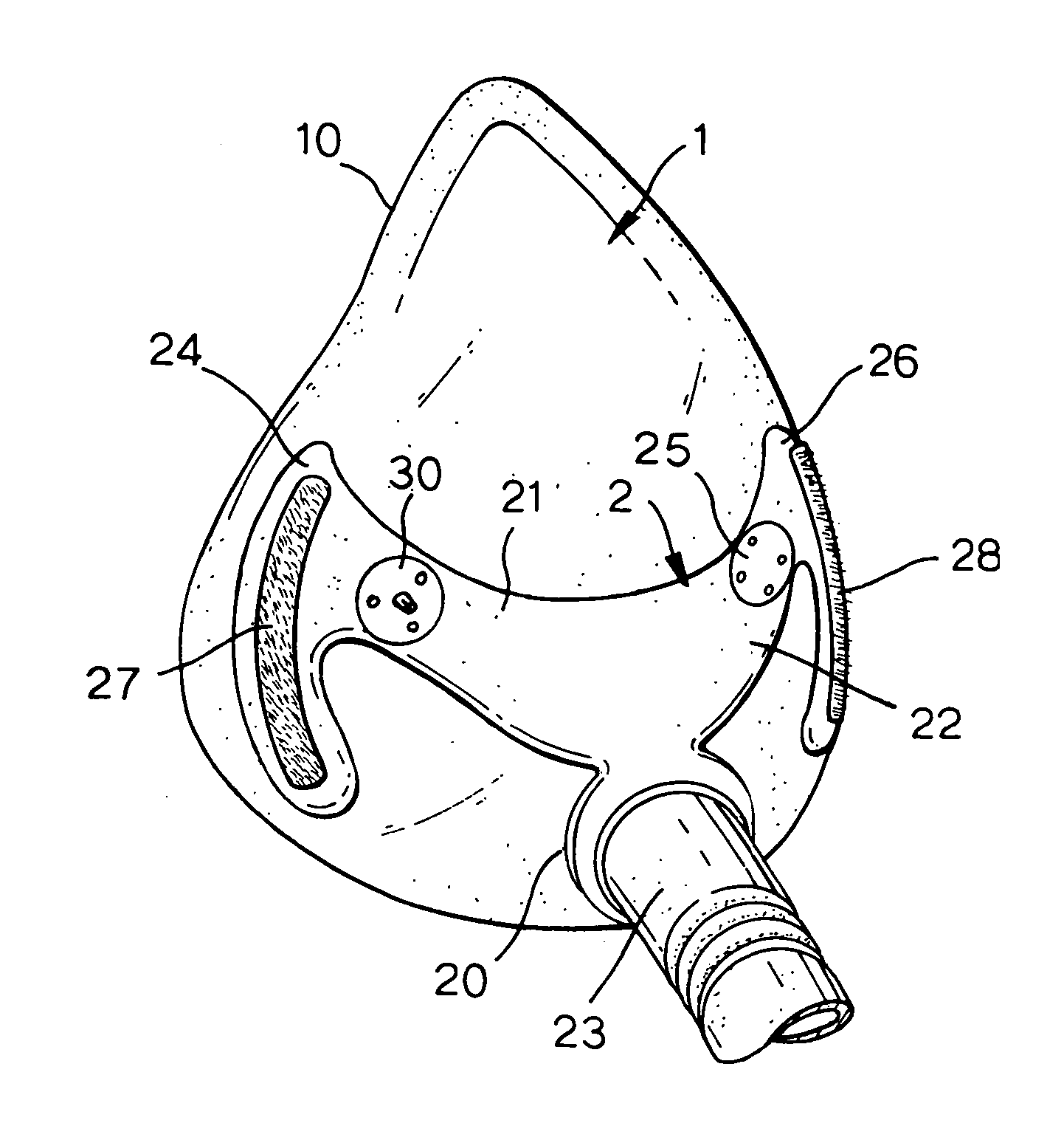
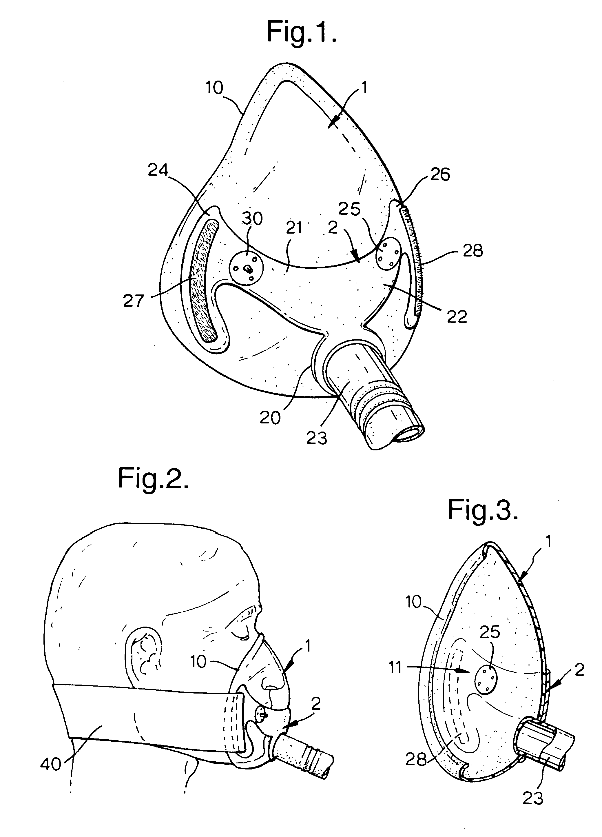
[0019] With reference first to FIGS. 1 to 5, the mask comprises two parts, namely a canopy 1 and a support frame 2. The canopy 1 is moulded of a relatively soft, flexible plastics material, such as, SEBS styrene ethylene butadiene styrene, whereas the support frame 2 is moulded of a harder material, such as a polypropylene copolymer. The canopy 1 and support frame 2 are moulded integrally with one another by a dual-shot moulding process in which the higher temperature plastics material forming the frame 2 is moulded first in a mould cavity, then the mould is enlarged to form a cavity for the canopy, which is subsequently moulded from a lower temperature plastics material. This results in the canopy and support frame being integrally bonded together.

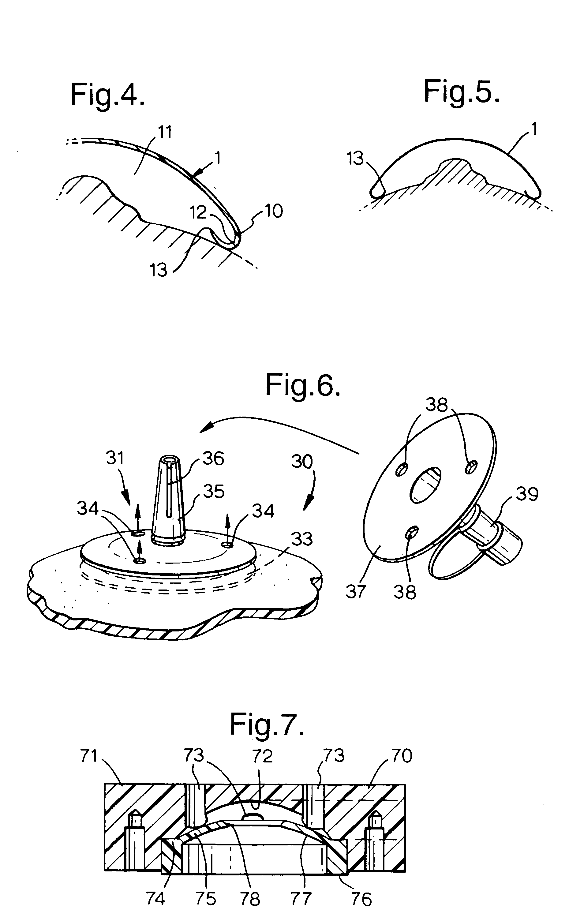
[0020] The canopy 1 is of generally triangular shape with a peripheral edge 10 shaped to extend under the mouth, up the cheeks, along the sides and across the nose. The canopy 1 has a domed internal cavity 11 in which the nose is receive...


PUM

PropertyMeasurementUnit
Temperatureaaaaaaaaaa
Thicknessaaaaaaaaaa
Flow rateaaaaaaaaaa

Abstract

A face mask has a relatively soft canopy and a more rigid reinforcement member moulded together from different plastics as two shots in a dual-shot moulding process. The peripheral sealing edge of the canopy is tapered to a reduced thickness to increase its flexibility. The reinforcement member is a frame with radially-extending arms supporting respectively a gas port by which gas can enter the mask, a valve that allows air into the mask when there is an inadequate supply at the gas port and a selectively closable vent. The mask is secured to the patient's head by a harness attached to ends of the harness arms.

Description

BACKGROUND OF THE INVENTION [0001] This invention relates to face masks. [0002] Face masks are used to supply gas to a patient for various purposes and are designed to seal with the skin surface around the nose and mouth. There are many different forms of face mask currently available but often these suffer from disadvantages such as large bulk, weight, discomfort in use or poor sealing. BRIEF SUMMARY OF THE INVENTION [0003] It is an object of the present invention to provide an alternative face mask. [0004] According to one aspect of the present invention there is provided a face mask of a plastics material comprising a relatively soft canopy member having a peripheral sealing edge providing a seal with the skin around the nose and mouth of a patient, the canopy member being moulded as one shot in a dual-shot moulding process, a relatively rigid reinforcement member being moulded integrally with the canopy member as another shot in the dual-shot moulding process, and the mask havin...

Claims


Application Information

Patent Timeline
IPC IPC(8): A61J15/00A61M16/06A61M16/20B29C45/16
CPCA61M16/06A61M16/0683B29C45/1676A61M16/209A61J15/0003A61M16/0616B29C2791/001A61M16/206A61M16/208A61M2202/0225A61M2202/0085A62B18/00B29C39/10B29C45/14B29C70/76
Inventor NASH, JOHNWILLIAMS, LOIS REBECCANEAME, SIMONPAGAN, ERICBISHOP, GILES ANDREWBOWER, DAVIDSTINTON, CLIVE
Owner SMITHS GRP PLC
Why Eureka
Try Eureka