Improved electronic control for railway airbrake

a technology of electronic control and airbrake, which is applied in the field of railway industry, can solve the problems of difficult maintenance of the unit in the field, and the extreme hardness of the sensitive computer electronics which control the device, and achieve the effect of improving physical configuration and being easy to repla

Inactive Publication Date: 2005-05-12
WESTINGHOUSE AIR BRAKE TECH CORP
View PDF18 Cites 31 Cited by
  • Summary
  • Abstract
  • Description
  • Claims
  • Application Information

AI Technical Summary

Benefits of technology

[0010] The air brake of the present invention has an improved physical configuration that allows failed components to be more easily replaced. Components are grouped together into field replaceable units by function. This allows for easy diagnosis o

Problems solved by technology

Prior art electronic air brake controls are known to have various deficiencies.
First, some units in the field are difficult to maintain because of the complexity of the units and the difficulty of replacing parts on the units due to the many electronic and pneumatic con

Method used


Image

  • Improved electronic control for railway airbrake
  • Improved electronic control for railway airbrake
  • Improved electronic control for railway airbrake

Examples


Embodiment Construction

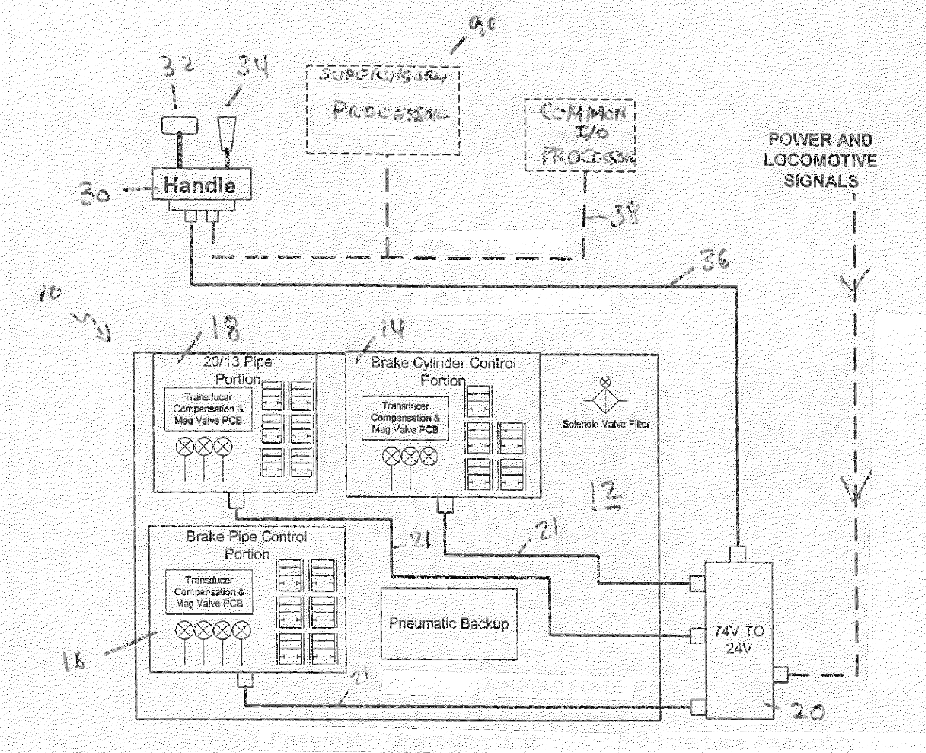
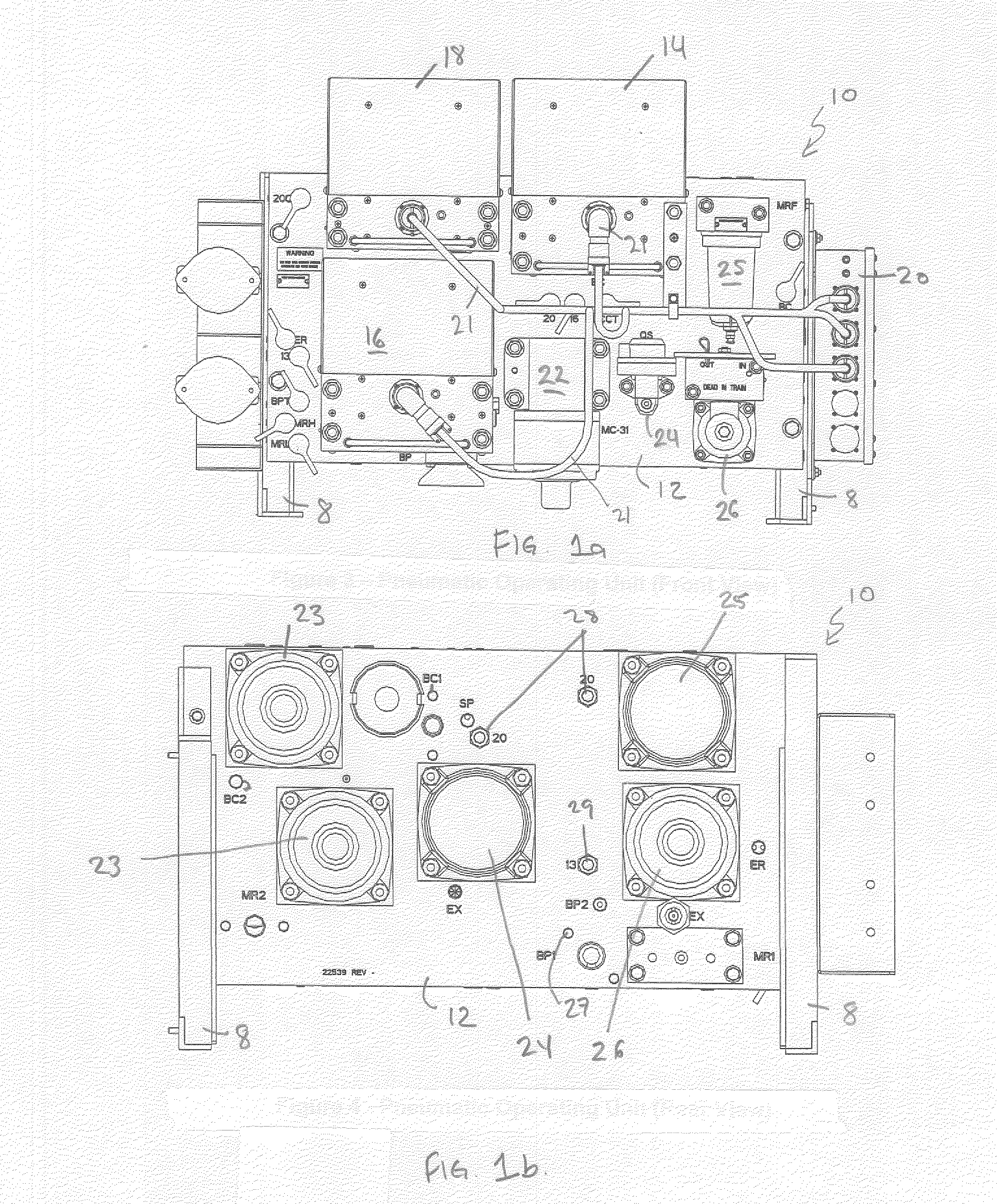
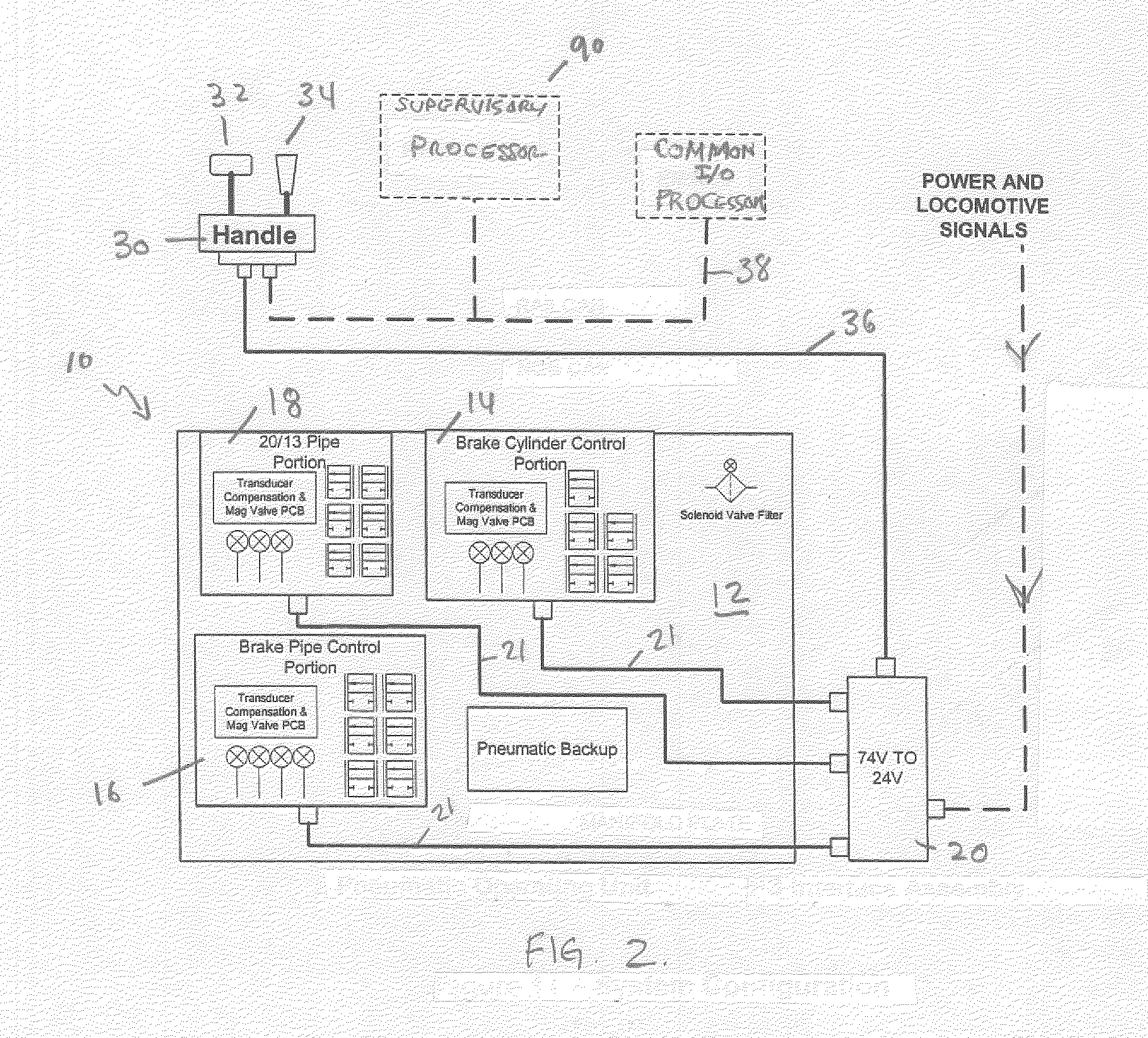
[0023] The air brake control described herein is made up of two major components, handle unit 30 and pneumatic operating unit 10. Handle unit 30 is typically located in the cab of a locomotive and is accessible by the engineer during normal operations. Pneumatic operating unit 10 is typically located in the air brake equipment locker under the cab of the locomotive.

[0024] Handle unit 30 has controls consisting of automatic brake handle 32 and independent brake handle 34. Automatic brake handle 32 controls pressure in the BP, which, in turn, controls the braking of all cars in the train, including locomotives in the train consist. Independent handle 34 controls the pressure in the IAR and ACT pipes, which in turn, controls the braking of the lead locomotive and additional locomotives in the train consist independently from automatic brake handle 32 and the rest of the train.

[0025] The air brake control in a locomotive in a typical train is set up in one of several modes, depending ...


PUM


Abstract

An electronic control for a locomotive airbrake featuring field replaceable control portions having a minimum of pneumatic and electrical connections which are controlled by a redundant, distributed network of microprocessors.

Description

RELATED APPLICATIONS [0001] This application claims the benefit under 35 U.S.C. 1.19(e) of U.S. Provisional Application 60 / 519,391, filed Nov. 12, 2003.FIELD OF THE INVENTION [0002] This invention is related to the railway industry, and in particular, the control of pneumatic brakes for railway vehicles. BACKGROUND OF THE INVENTION [0003] The basic railway triple valve pneumatic airbrake was invented by George Westinghouse over one hundred years ago and the functions of that brake are still in operation today on many railway freight vehicles. [0004] The basic idea of the triple valve airbrake is to use a pressurized pneumatic line to propagate braking control signals from the train locomotive to all other vehicles in the train. The pneumatic line, known as the brake pipe (BP), runs the length of the train and is coupled to air reservoirs on each car. The system is charged to an operating state by pressurizing the BP, thus filling the reservoirs on each car with pressurized air. When...

Claims


Application Information

Patent Timeline
IPC IPC(8): B60T13/66B60T17/04
CPCB60T13/662B60T17/04B60T13/665
Inventor HOLLANDSWORTH, PAULSINGLETON, STEVETUBERGEN, GARY
Owner WESTINGHOUSE AIR BRAKE TECH CORP
Why Eureka
Try Eureka