Magnetic coupling using magnets on a motor rotor

Inactive Publication Date: 2005-05-12
GERFAST STEN R
View PDF8 Cites 12 Cited by
  • Summary
  • Abstract
  • Description
  • Claims
  • Application Information

AI Technical Summary

Benefits of technology

[0027] In a comparative test, using the same magnetic flux and the same spacing of the drive/driven assemblies, between the present invention and other existing magnetic couplings, the present invention would also be more efficient because of its lower frictional losses in its fewer parts.
[0028] The advantage of any magnetic coupling is that since there is no mechanical connection between the drive and the driven part, a membrane c

Problems solved by technology

These two sets of multiple magnet assemblies, a multitude of bearings,

Method used


Image

  • Magnetic coupling using magnets on a motor rotor
  • Magnetic coupling using magnets on a motor rotor

Examples


Embodiment Construction

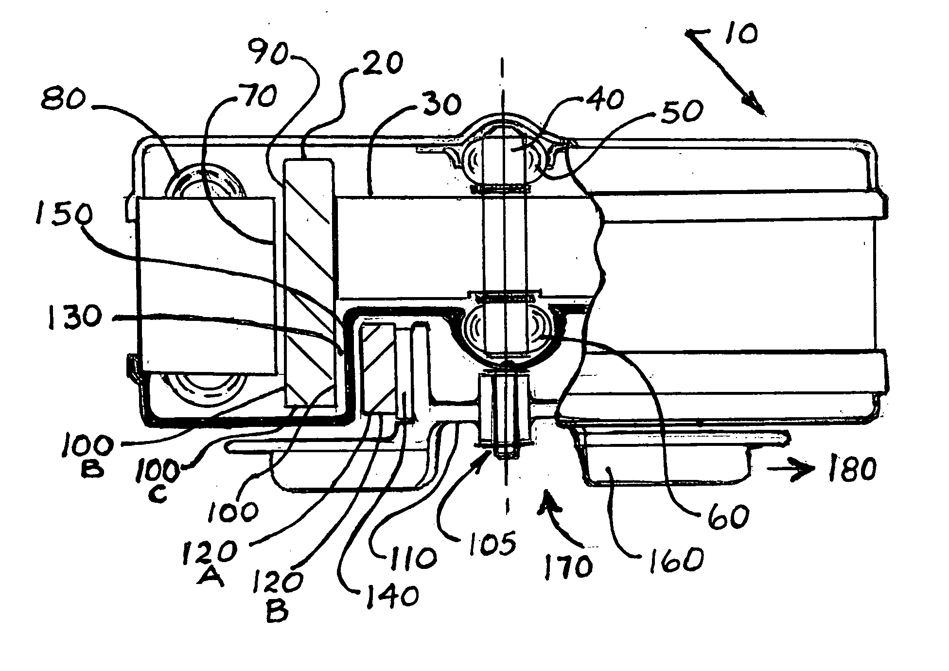
[0035]FIG. 1 illustrates one possible embodiment of the present invention 10 using an electric motor's permanent magnets 20 mounted in a cylindrical fashion on the motor rotor 30 having a shaft 40 that is journalled on bearings 50 and 60. The permanent magnets 20 could be a solid cylindrical ring, but is more often made up from semi-cylindrical magnet segments into a cylindrical ring, and will be described as segments 20.

[0036] These magnet segments 20 are co-acting with the motor's stator-face 70 to produce torque when the stator's windings 80 are energized. The stator-face 70 is substantially cylindrical. The magnet segments 20 has a semi-cylindrical face 90 facing the stator-face 70 and also has a semi-cylindrical inside face 100. This magnet face 100 and its magnetic flux is in this embodiment used for coupling to a second rotor.

[0037] In alternate embodiments of the present invention the magnet segment face 100 B which is an outside semi-cylindrical face, and 100 C which is a...


PUM


Abstract

A simplified magnetic coupling utilizing the available rotating permanent magnets on an electric motor rotor to be the “drive” component in the magnetic coupling of the present invention. The “driven part of the magnetic coupling is a co-axially journalled second rotor, driven by magnetic flux from the rotating permanent magnets on the motor rotor mentioned above. A membrane between these two rotors can hermetically separate the drive part from the driven part. This invention has fewer parts, has both less costly parts and assembly and is also more compact then related art.

Description

TECHNICAL FIELD [0001] This invention relates to magnetic couplings or clutches, and relates to torque-transmission using magnetic flux, generally between disc's, or rotating components across an air gap. [0002] The rotating, non-contacting, components could be separated by a membrane that is enclosing some of these components hermetically. The output component could be used for driving a mechanical device, or a pump for pumping a gas or liquids. DESCRIPTION OF RELATED ART [0003] Most systems available today for transmission of torque by magnetic methods are consisting of three or more basic parts with their sub-assemblies: Motor, Input (drive) disc and Output (driven) disc. The motor or engine with it's output shaft is sometimes connected to the drive disc with a flexible coupling to allow for a small amount of misalignment between the shaft from the rotor to the magnetic disc drive assembly. [0004] The drive assembly is generally supported on it's own bearings, separate from the m...

Claims


Application Information

Patent Timeline
IPC IPC(8): H02K5/10H02K7/11H02K21/14H02K49/10
CPCH02K7/11
Inventor GERFAST, STEN R.
Owner GERFAST STEN R
Why Eureka
Try Eureka