AC motor having stator windings formed as loop coils, and control apparatus for the motor

a technology of ac motor and stator winding, which is applied in the direction of magnetic circuits characterised by magnetic materials, magnetic circuit shapes/forms/construction, magnetic circuit rotating parts, etc., can solve the problems of low manufacturing productivity, difficult to produce such a brushless motor in a compact size, and difficult to manufacture such a brushless motor at low cost, so as to simplify the construction of the stator and simplify the assembly of the stator. , the effect of increasing the output torqu

Active Publication Date: 2005-05-12
DENSO CORP
View PDF9 Cites 54 Cited by
  • Summary
  • Abstract
  • Description
  • Claims
  • Application Information

AI Technical Summary

Benefits of technology

[0033] As a further aspect of the invention, one or more of the loop-configuration stator windings may be shaped as a loop that extends partially around the inner circumference of the stator and partially extends along the rotor axis direction, i.e., with one or more of the stator poles protruding through the central aperture of the loop. This has the advantage that assembling of the stator can be simplified.
[0034] As a further aspect, such a synchronous AC motor may be formed with the respective pole faces of the stator poles each having a dimension, as measured along the rotor axis direction, which is longer than the pitch of the stator pole groups. This enables the stator poles...

Problems solved by technology

However such a brushless motor has a complex construction, due to the need to form windings around each of the respective stator poles, with each of the windings being disposed in the in...

Method used


Image

  • AC motor having stator windings formed as loop coils, and control apparatus for the motor
  • AC motor having stator windings formed as loop coils, and control apparatus for the motor
  • AC motor having stator windings formed as loop coils, and control apparatus for the motor

Examples


Embodiment Construction

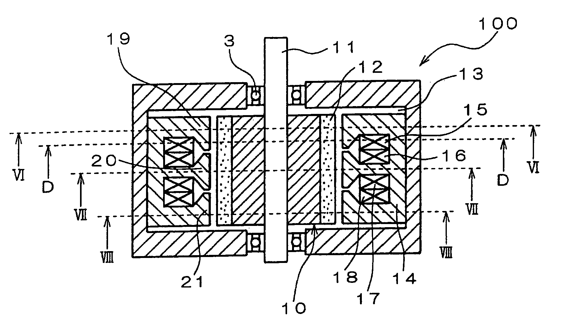
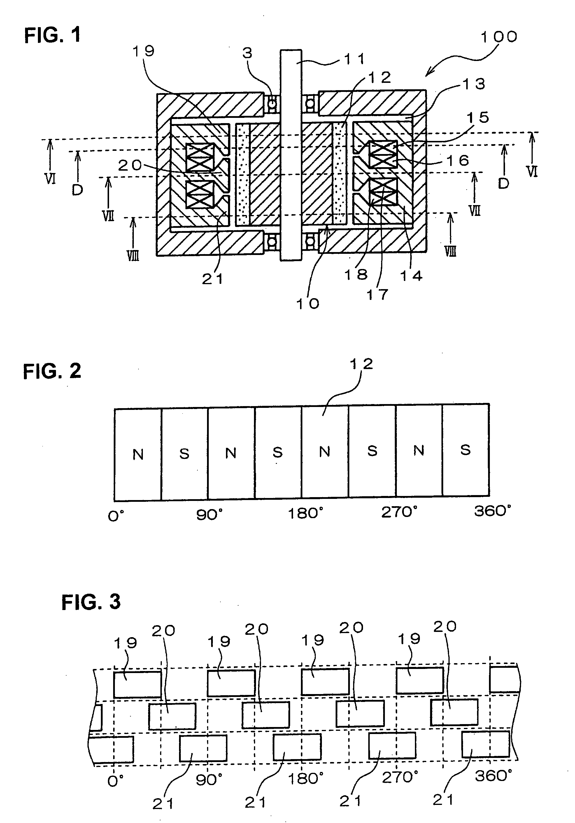
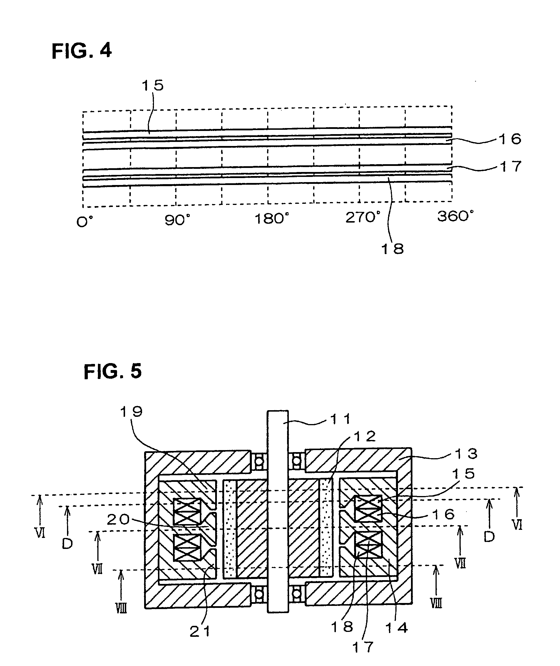
[0078]FIG. 1 is a cross-sectional view taken along the motor shaft of an embodiment of a brushless motor, designated by numeral 100. This is a 3-phase 8-pole motor having a rotor shaft 11 mounted on bearings 3, a rotor 10 having permanent magnets 12, and a stator 14, with these being enclosed in a housing 61.

[0079] The rotor 10 has the permanent magnets 12 disposed circumferentially around its periphery, with N poles and S poles arranged in successive alternation, as shown in the developed circumferential view of FIG. 2, taken around the outer periphery of the rotor 10. The 360° circumference of the rotor 10 is equivalent to an electrical angle of 1440°.

[0080] The stator 14 is provided with four U-phase stator poles 19, four V-phase stator poles 20, and four W-phase stator poles 21, each of which projects radially inward towards the periphery of the rotor 10. FIG. 3 is a developed circumferential view of the stator 14, illustrating the position relationships between these stator p...


PUM


Abstract

A synchronous AC motor has a stator with stator poles arranged as a plurality of circumferentially extending stator pole groups, with each stator pole group having a pair of corresponding circumferentially extending loop-configuration stator windings disposed adjacent on either side or a single such winding disposed adjacent at one side, adjacent stator pole groups being mutually circumferentially displaced by a fixed amount corresponding to a specific electrical phase angle. A rotating magnetic field is produced by applying respective polyphase AC voltages to the windings, such that currents of mutually opposite direction flow in each pair.

Description

BACKGROUND OF THE INVENTION [0001] 1. Field of Application [0002] The present invention relates to a synchronous AC motor, suitable for installation in a motor vehicle, and to a control apparatus for the AC motor. [0003] 2. Description of Prior Art [0004] In the prior art, types of synchronous AC motor, and in particular types of brushless AC motor, are known which have stator windings formed as closely packed layers of conductors that are wound around the stator poles, for example as described in Japanese Patent Laid-open No. 6-261513 (page 3, and FIGS. 1 to 3), designated in the following as reference document 1. FIGS. 40 and 41 are cross-sectional views taken along the motor shaft and at right angles to the motor shaft, respectively, showing the general configuration of such a prior art type of brushless motor. This example is a 4-pole 6-slot type of brushless motor, having compensating windings formed on the stator, and with respective stator windings of the phases (referred to ...

Claims


Application Information

Patent Timeline
IPC IPC(8): H02K29/06H02K1/02H02K1/27H02K15/02H02K19/00H02K19/02H02K21/04H02K21/12H02K21/14H02K37/00H02P6/06H02P6/08H02P6/10H02P6/28
CPCH02K21/145
Inventor NASHIKI, MASAYUKI
Owner DENSO CORP
Why Eureka
Try Eureka