Plasma display apparatus
a technology of display apparatus and plasma, which is applied in the direction of electrical apparatus casings/cabinets/drawers, television systems, instruments, etc., can solve the problems of large heat and electromagnetic interference (emi) generation, unstable signal processing, and leakage of heat and electromagnetic interference to the outside, so as to effectively dissipate the heat generated by the device, block the transfer of heat, and reduce noise
- Summary
- Abstract
- Description
- Claims
- Application Information
AI Technical Summary
Benefits of technology
Problems solved by technology
Method used
Image

Examples
first embodiment
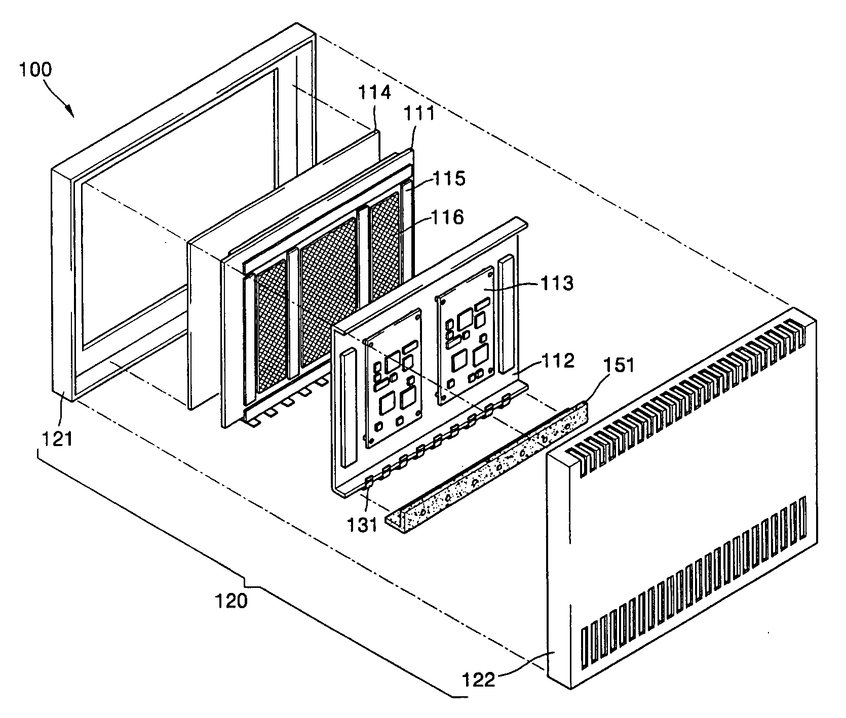
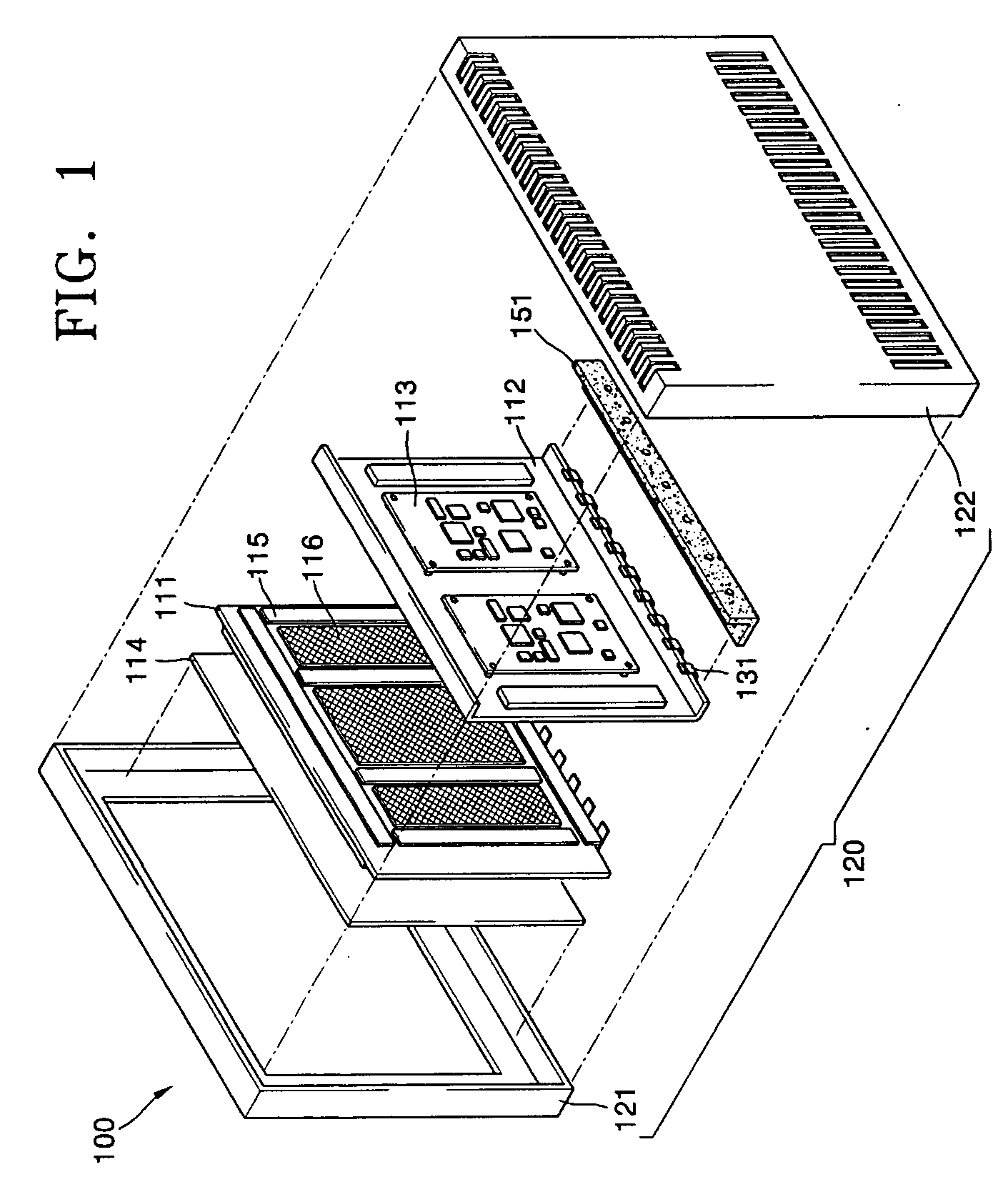
[0024]FIG. 1 is an exploded perspective view of a plasma display apparatus according to the present invention, and FIG. 2 is a side cross-sectional view of the plasma display apparatus of FIG. 1.
[0025] Referring to FIGS. 1 and 2, the plasma display apparatus 100 according to the first embodiment of the present invention includes a panel 111, a chassis base 112 that supports the panel 111, and a circuit board 113 disposed on a rear of the chassis base 112.
[0026] The panel 111 includes a front panel and a rear panel.
[0027] The front panel comprises a plurality of strip shaped sustain electrodes, bus electrodes connected to each of the sustain electrodes, a front dielectric layer that buries the sustain electrodes and the bus electrodes, and a protective layer coated on a surface of the front dielectric layer. The rear panel, which is coupled to the front panel with a space sealed between the front panel and the rear panel, comprises a plurality of address electrodes perpendicular to...
second embodiment
[0042]FIG. 4 is a cross-sectional view of a plasma display apparatus according to the present invention. The description of elements included in both FIG. 2 and FIG. 4 will be omitted since like reference numerals refer to like elements.
[0043] Referring to FIG. 4, the reinforcing member 141 included in the first embodiment is omitted from the plasma display apparatus 200 according to the second embodiment.
[0044] More specifically, an end of a TCP 211 is connected to the panel 111 via a chassis base 112, and the other end of the TCP 211 is connected to a circuit board 113, while a device 212 mounted on the TCP 211 is disposed on a bent portion 112a of a chassis base 112.
[0045] A heat transfer member 162 is disposed on an exposed outer surface of the device 212, which is mounted on the TCP 211, and disposed on the chassis base 112, and a protection plate 221 is mounted on an outer surface of the heat transfer member 162.
[0046] The protection plate 221 has a 90° bend to protect both...
third embodiment
[0049]FIG. 5 is a cross-sectional view of a plasma display apparatus according to the present invention.
[0050] Referring to FIG. 5, the plasma display apparatus 300 according to the present embodiment includes a chassis base 311 which, unlike the chassis base 112 of FIGS. 2 and 4, does not have a bent portion 112a.
[0051] More specifically, an end of a TCP 321 is connected to the panel 111 via an end of the chassis base 311, and the other end of the TCP 321 is connected to a circuit board 113. A device 322 mounted on the TCP 321 is disposed on an edge of the chassis base 311. A heat transfer member 162 is disposed on an exposed exterior of the device 322, which is mounted on the TCP 321, and a protection plate 331 is disposed on an outer surface of the heat transfer member 162.
[0052] The protection plate 331 is formed of a leaf member which is parallel to the chassis base 311, but is not limited thereto. The protection plate 331 can be bent at 90°, as in the previous embodiments. T...
PUM
 Abstract
Description
Claims
Application Information
 - R&D
- Intellectual Property
- Life Sciences
- Materials
- Tech Scout
- Unparalleled Data Quality
- Higher Quality Content
- 60% Fewer Hallucinations
Browse by: Latest US Patents, China's latest patents, Technical Efficacy Thesaurus, Application Domain, Technology Topic, Popular Technical Reports.
© 2025 PatSnap. All rights reserved.Legal|Privacy policy|Modern Slavery Act Transparency Statement|Sitemap|About US| Contact US: help@patsnap.com