
Method and apparatus for precision changing of micropipettes

a technology of precision changing and micropipettes, applied in the field of micropipettes, can solve the problems of difficult and time-consuming finding the tip of a pipette under the microscope, difficult positioning and exchange of micropipettes, and complicated procedures, and achieve the effect of convenient rapid and precise replacement and repositioning

Inactive Publication Date: 2005-05-12
SUTTER INSTR
View PDF1 Cites 1 Cited by
  • Summary
  • Abstract
  • Description
  • Claims
  • Application Information

AI Technical Summary

Benefits of technology

[0007] Accordingly, it is an object of the present invention to provide a method and apparatus for precisely repositioning a micropipette at a desired location that takes into account manufacturing variability in the length of pipettes.
[0008] It is another object of the present invention to provide a method of using a programmable micromanipulator to facilitate the rapid and precise replacement and repositioning of micropipettes.

Problems solved by technology

Since the working distance and the field of view of commonly used microscope objectives are both very small, finding the tip of a pipette under the microscope is difficult and time consuming.
Certain complex biological experiments make micropipette positioning and exchange even harder because other items (additional pipettes, perfusion tubes) may be placed near the pipette in a small space.
These factors make pipette exchange a frequent occurrence, while the procedure is simultaneously difficult and tedious.
However, in practice it is quite difficult to automatically and precisely reposition micropipettes because of variability in pipette lengths.
However, without extra quality control and / or manufacturing methods usually not found in the laboratory environment it is unlikely that the length of pipettes can be easily or inexpensively controlled with greater precision.

Method used


Image

  • Method and apparatus for precision changing of micropipettes
  • Method and apparatus for precision changing of micropipettes
  • Method and apparatus for precision changing of micropipettes

Examples


Embodiment Construction

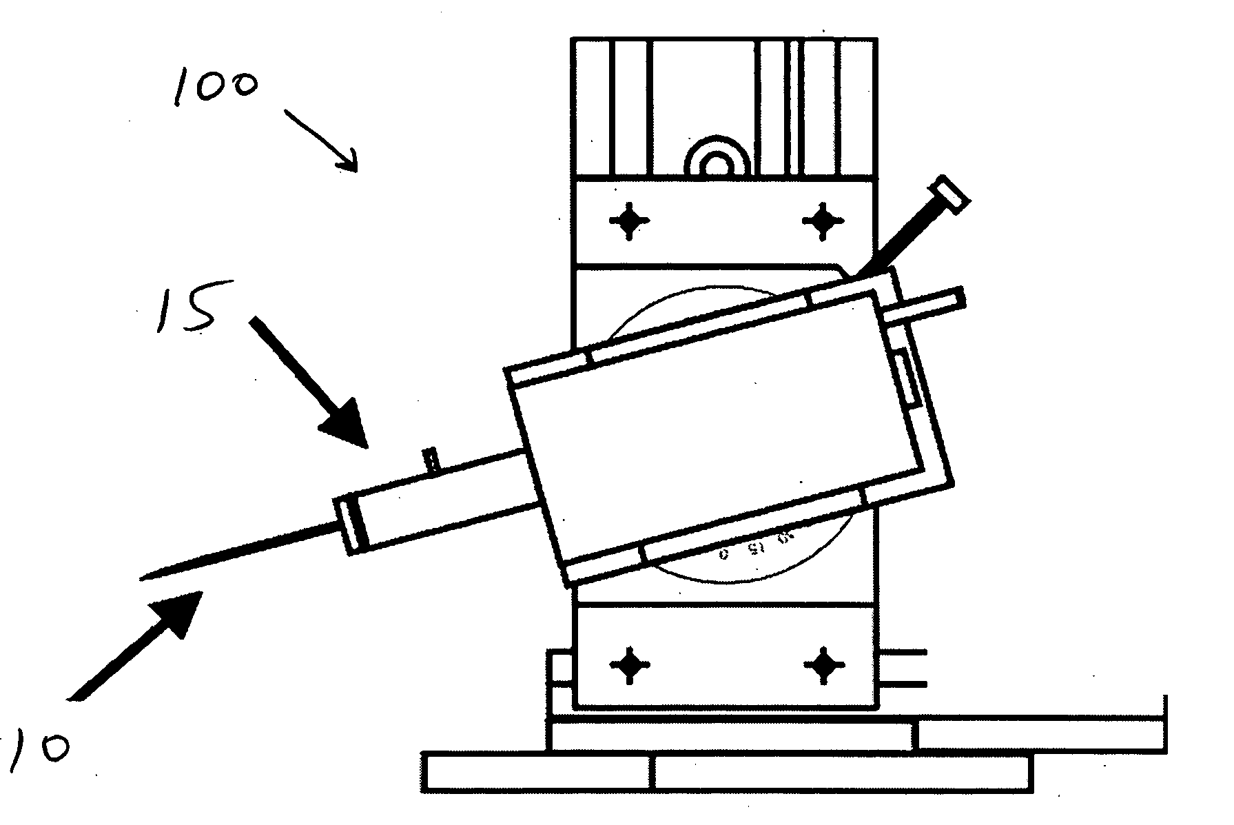
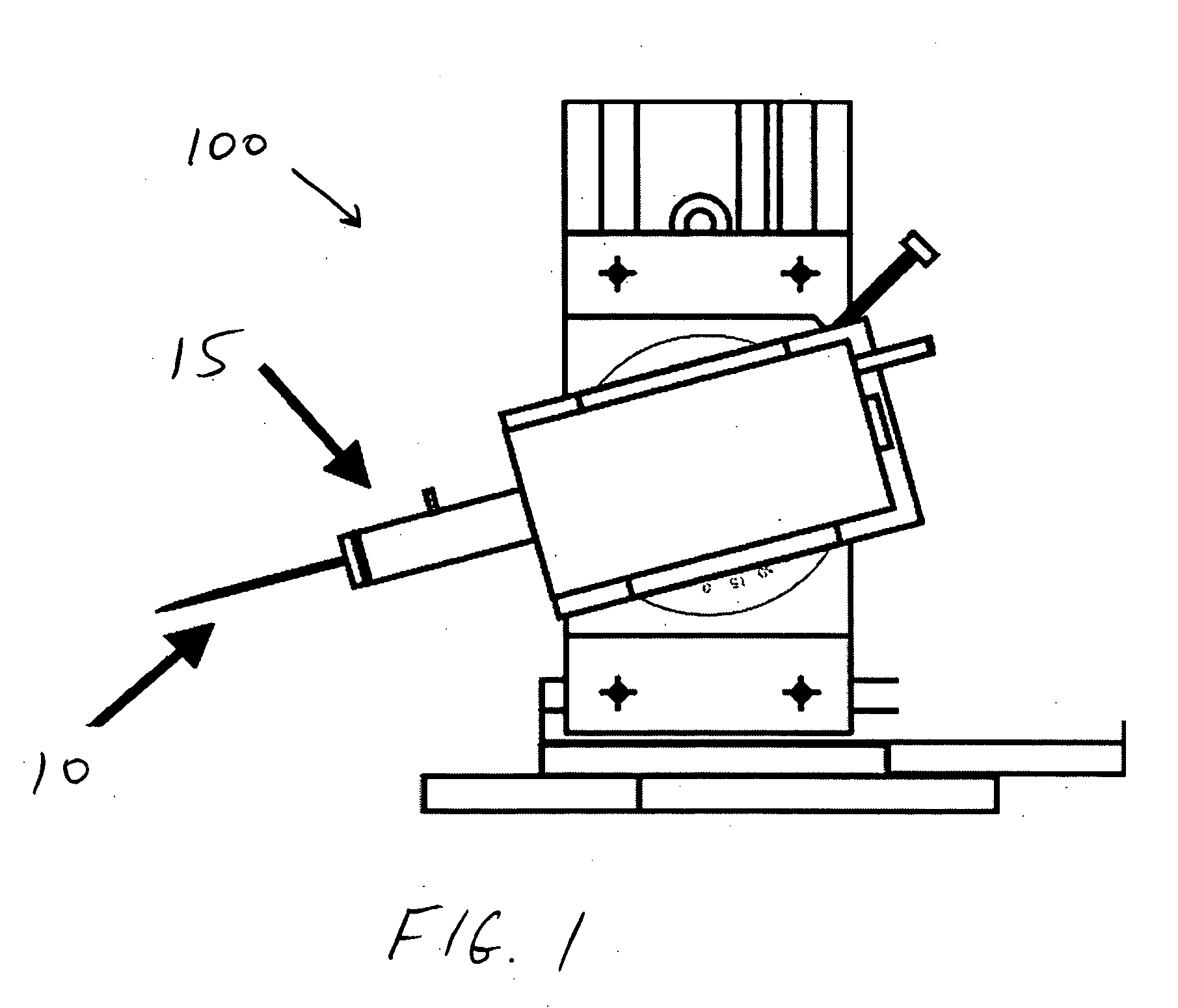
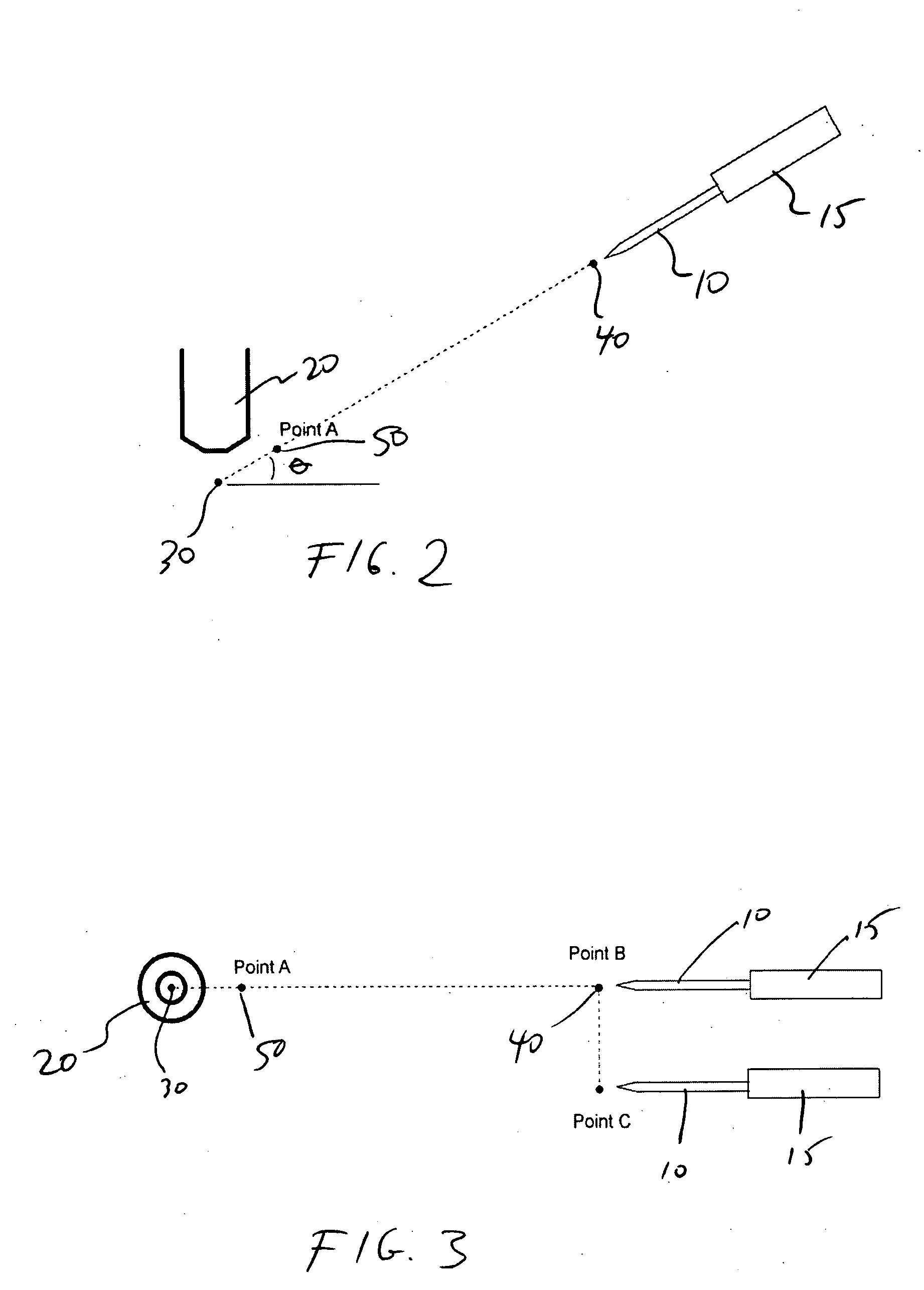
[0012] The present invention relates to an apparatus and method of automated pipette repositioning that allows for the variability in the length of pipettes produced by standard methods. According to the invention, a “corrected path” is defined, comprising a set of movements that allows pipettes of controlled, but variable length to be repositioned in the field of view without causing broken pipette tips or damage to the biological specimen under investigation. Such a method is of value to the field as most experimenters will avoid using automated pipette repositioning if it might risk damage to the preparation or the pipette. In a preferred embodiment the present invention defines the corrected path and its implementation using a programmable motorized micro-manipulator.

[0013] The present invention comprises a micromanipulator and a method of using the micromanipulator. FIG. 1 shows a micromanipulator 100 having a pipette holder 15 in which a micropipette 10 is positioned. Microma...


PUM


Abstract

A semi-automated method of replacing micropipettes using a micromanipulator is disclosed. A first micropipette is moved at a known angle from a work position to a distal position under automatic control of the micromanipulator. A replacement micropipette is then mounted in the micromanipulator and is moved under automatic control to a position proximate to the work position. The distance between the work position and the proximate position is substantially equal to the range of manufacturing variability of the micropipettes. The second micropipette is then moved by manual control of the micromanipulator from the proximate position to the work position by moving it in a linear path along the known angle so that the final approach to the work position can be visually monitored.

Description

FIELD OF THE INVENTION [0001] The present invention is directed to the use of micropipettes in scientific experimentation, and is particularly related to methods and apparatus for changing micropipettes to facilitate precise repositioning. BACKGROUND OF THE INVENTION [0002] Micropipettes are used in a variety of scientific experiments, such as intracellular recording, cell patching, and the like, which require very precise positioning of the tip of the micropipette with the aid of an optical microscope. The micropipettes may be used to record electrical signals within a cell or within a cell membrane, or to apply a desired electrical stimulus to a cell. In such applications, the micropipette is typically positioned at a desired location under visual observation with a microscope, using a micromanipulator. To initially position or reposition a micropipette, the experimenter has to find its tip in the microscope's field of view by coarse movement of a micromanipulator aided by visual ...

Claims


Application Information

Patent Timeline
IPC IPC(8): B01L3/02G01N35/10
CPCG01N35/1011
Inventor TANG, YUNGUIFLAMING, DALE GORDONAYER, RICHARD KELLOGG JR.BELGUM, JACK HENRIKSIEDENBURG, FREDERICK J.
Owner SUTTER INSTR
Learn More