Remote display ammeter for power plug or power strip

a technology of power plugs and ammeters, which is applied in the direction of measuring instruments, coupling device connections, instruments, etc., can solve the problems of difficult to reach the power strip, limited access to the power cord for monitoring the status of current or power usage, and awkward reach of the power strip

Inactive Publication Date: 2005-05-12
THE WIREMOLD CO
View PDF4 Cites 78 Cited by
  • Summary
  • Abstract
  • Description
  • Claims
  • Application Information

AI Technical Summary

Benefits of technology

[0017] Accordingly, the present invention seeks to provide a number of components along with a power strip having a T-shaped slot in the rear face so that the power strip can be mounted in / to a variety of enclosures, racks, and other surfaces so as not to require a skilled artisan for field installation.
[0018] Additionally, the present invention provides a power cord including a cable having a male plug connector attached at a first end of the cable and a female plug connector attached at a second end of the cable. One of the male and female plug connectors including a housing having a current sensor mounted therein and connected to the cable for detecting the electrical current flow therethrough. An ammeter housing is provided including a processing circuit and a display device mounted therein for displaying the status of the electrical draw through the power cord at a location remote from the power cord. For example, if the power cord is utilized on a floor or under machinery, the ammeter housing can be positioned in an accessible area for convenient viewing or monitoring of the status of the electrical draw through the power cord.

Problems solved by technology

In use, such conventional installations sometimes make it awkward to reach the power strip for purposes of plugging and unplugging equipment to the outlets provided in the power strip, and for checking the status of the power input to the cabinet itself.
In other applications, such as machinery or large appliances, power cords are usually located at the rear of or lower portion of the appliances or machines being powered such that access to the power cord for monitoring the status of the current or power usage is often limited.

Method used


Image

  • Remote display ammeter for power plug or power strip
  • Remote display ammeter for power plug or power strip
  • Remote display ammeter for power plug or power strip

Examples


Embodiment Construction

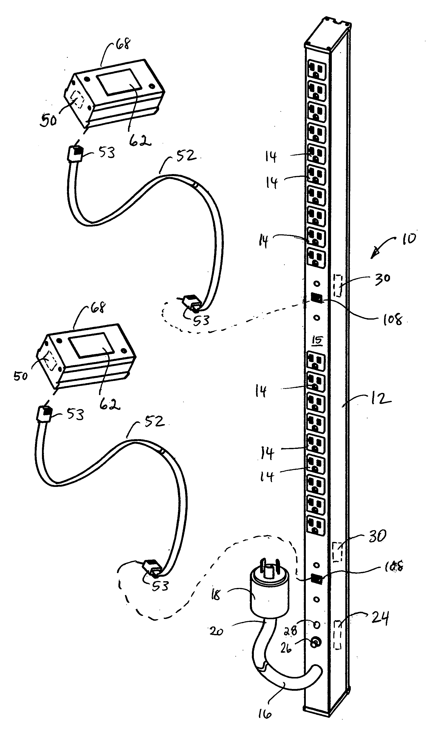
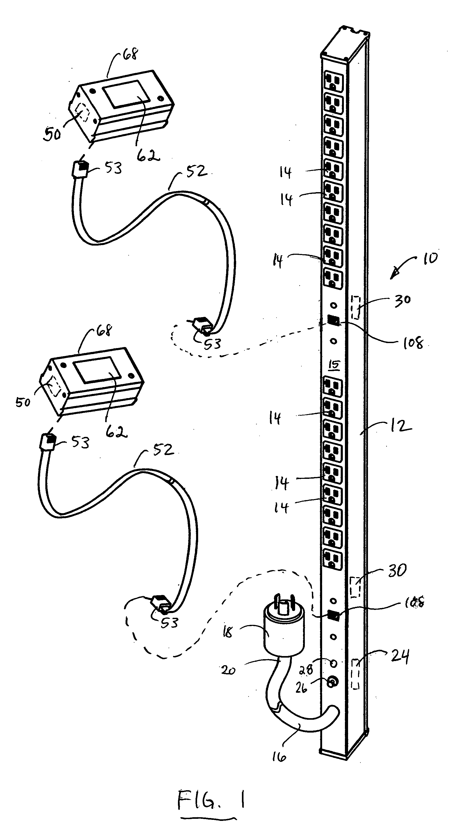
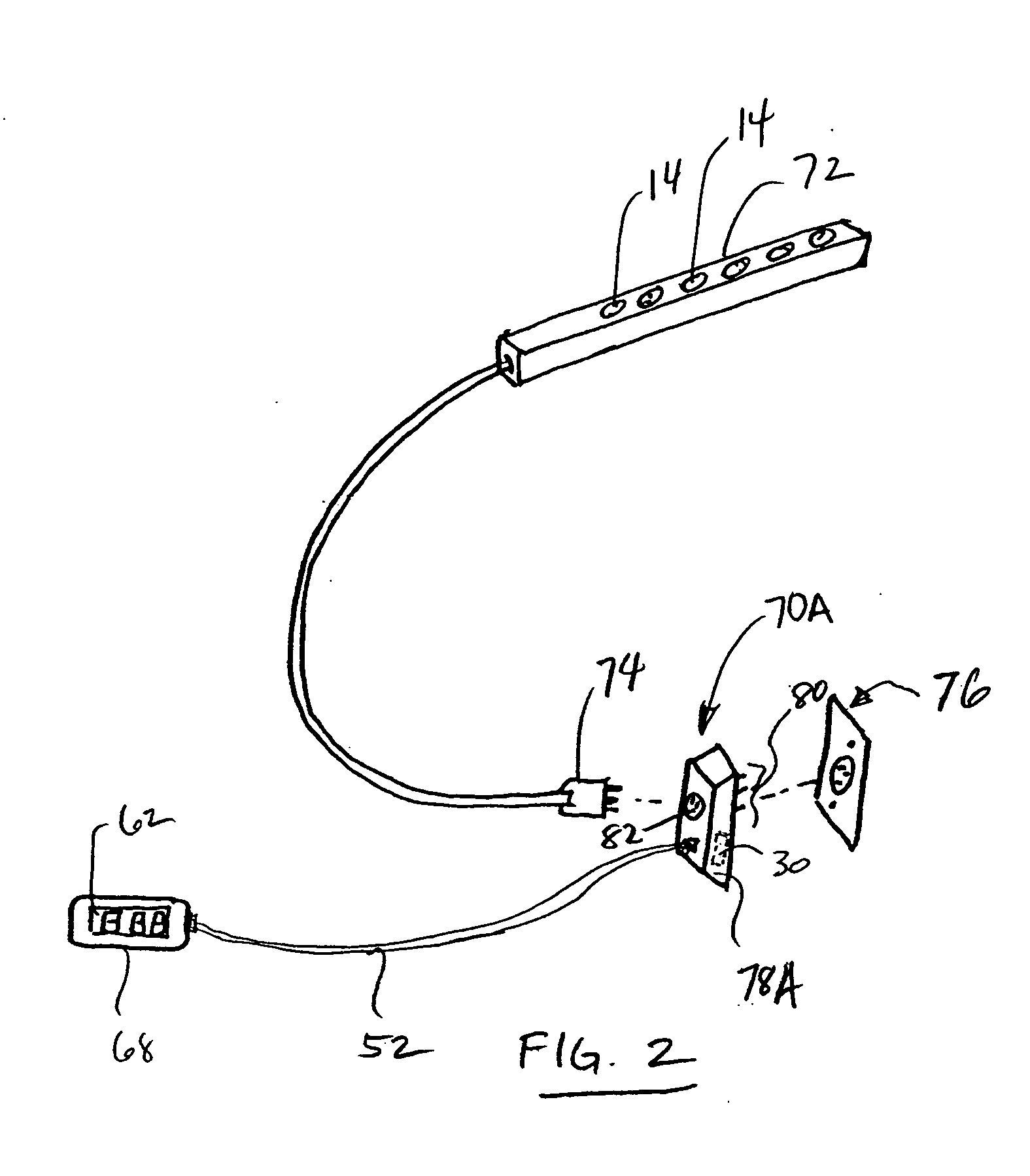
[0035] Referring to FIG. 1, an exemplary embodiment of a power strip in accordance with the present invention is shown generally at 10. The power strip 10 includes a housing 12 having a plurality of electrical outlets 14 mounted to a front face 15 of the housing. The electrical outlets 14 are electrically connected to a first end portion (not shown) of a power supply cord 16 in a conventional manner for providing electrical power to the outlets. A male plug 18 is attached to a second end 20 of the power supply cord 16. Typically, the male plug 18 is connected to an electrical outlet 76 (shown in FIG. 2) for providing electrical power to the power strip 10.

[0036] The power strip 10 includes a circuit breaker 24 also mounted to the front face 15 of the housing 12 and including a reset button 26 and overcurrent indicator 28. The circuit breaker 24 opens in the event of an overcurrent condition and provides overcurrent protection to electrical equipment associated with the power strip ...


PUM


Abstract

A power strip is providing including a housing coupled to a first end portion of a power supply cord, the housing having an electrical receptacle mounted thereto and connected to the power supply cord, the power supply cord having a second end connectable to a power source. A current sensor is coupled to the power supply cord between the electrical receptacle and the second end for detecting electrical current flow through the power supply cord and providing an output signal that varies in proportion to the current flow through the power supply cord. A processing circuit coupled to the output of the current sensor includes a display device for displaying at least one of the current, voltage, power, and phase associated with the power supply cord at the current sensor. The display device can be remotely coupled to the power strip for positioning the display in a convenient location.

Description

CROSS REFERENCE TO RELATED APPLICATIONS [0001] This application claims priority to U.S. Provisional Patent Application No. 60 / 519,434 filed on Nov. 12, 2003 entitled “Cabinet Mounting For Power Strip” and U.S. Provisional Patent Application No. 60 / 546,246 filed on Feb. 20, 2004 entitled “Remote Readout for Power Plug or Power Strip”. The disclosure of each of the above-identified provisional applications is incorporated herein by reference.FIELD OF THE INVENTION [0002] The present invention generally relates to power strips and power cords and more particularly to a power strip and power cord including a remote display ammeter. BACKGROUND OF THE INVENTION [0003] Electronic cabinets generally are provided with power strips built into the cabinet for ease in plugging in electronic equipment provided within the cabinet. Typically, such power strips are permanently mounted on the back of the cabinet which makes the power strip accessible from the rear of the cabinet, the cabinet typical...

Claims


Application Information

Patent Timeline
Patent Type & Authority Applications(United States)
IPC IPC(8): G01R1/04G01R19/00H01R13/66H01R25/00
CPCG01R1/04G01R19/0092H01R24/64H01R25/00H01R2201/20H01R13/6683
Inventor GODARD, JEAN LUC
Owner THE WIREMOLD CO
Why Eureka
Try Eureka