
Portable electronic apparatus with azimuth measuring function, magnetic sensor suitable for the apparatus, and azimuth measuring method for the apparatus

Inactive Publication Date: 2005-05-12
SATO HIDEKI
View PDF19 Cites 1 Cited by
  • Summary
  • Abstract
  • Description
  • Claims
  • Application Information

AI Technical Summary

Benefits of technology

[0009] Another object of the invention is to provide a direction measuring method capable of measuring a direction at high precision by estimating the influence of the magnetic field of permanent magnets of the apparatus upon the magnetic sensor unit with simple user operations.
[0014] By measuring the influences of the magnetic field of the permanent magnets at the first and second temperatures, the influence at another temperature can be estimated. Accordingly, the direction can be measured at high precision while the number of operations to be performed by the user for the influence estimation is reduced. According to experiments, the magnetic field of the permanent magnets of a portable electronic apparatus is approximately in proportion to the temperature of the permanent magnets. Accordingly, the influence at the temperature of the present time can be estimated easily through linear interpolation or extrapolation of the influences at the first and second temperatures relative to the temperature.
[0017] If the influences at the first and second temperatures are acquired in the above manner, it is possible to prevent the measurement error contained in the measurements of the influences from greatly degrading the estimation precision of the influence at another temperature. Since the user is notified the time when the influence is measured at the second temperature, it is possible to avoid unnecessary initialization operations.
[0019] It is possible to provide a magnetic sensor which is compact, inexpensive and capable of compensating the influence of the magnetic field of the permanent magnet upon the direction measurement relative to the temperature of the permanent magnets, and is suitable for the portable electronic apparatus having permanent magnets.
[0023] It is possible to provide a magnetic sensor which is more compact, capable of processing signals in the form of digital signals, and is suitable for the portable electronic apparatus.
[0025] The geomagnetism of the same amplitude and opposite directions is applied to the magnetic sensors before and after the portable electronic apparatus is rotated by 180°. Therefore, each sum of the outputs of the magnetic sensors before and after the portable electronic apparatus is rotated by 180° is independent from the geomagnetism, and corresponds to the influence of the magnetic field of the permanent magnets upon the outputs of the magnetic sensors. By using this sum, the influence of the magnetic field of the permanent magnets can be estimated easily and at high precision. By determining the direction in the above manner, the direction can be measured easily and at high precision.

Problems solved by technology

There arises therefore a problem that the direction determined from the signal output from the magnetic sensor unit is not precise.
If the signal of the magnetic sensor unit is corrected only by the influence of the magnetic field of the magnet detected at one temperature on the signal of the magnetic sensor, and the direction is determined from the corrected signal, the determined direction is not correct when the temperature of the magnet changes.

Method used


Image

  • Portable electronic apparatus with azimuth measuring function, magnetic sensor suitable for the apparatus, and azimuth measuring method for the apparatus
  • Portable electronic apparatus with azimuth measuring function, magnetic sensor suitable for the apparatus, and azimuth measuring method for the apparatus
  • Portable electronic apparatus with azimuth measuring function, magnetic sensor suitable for the apparatus, and azimuth measuring method for the apparatus

Examples


Embodiment Construction

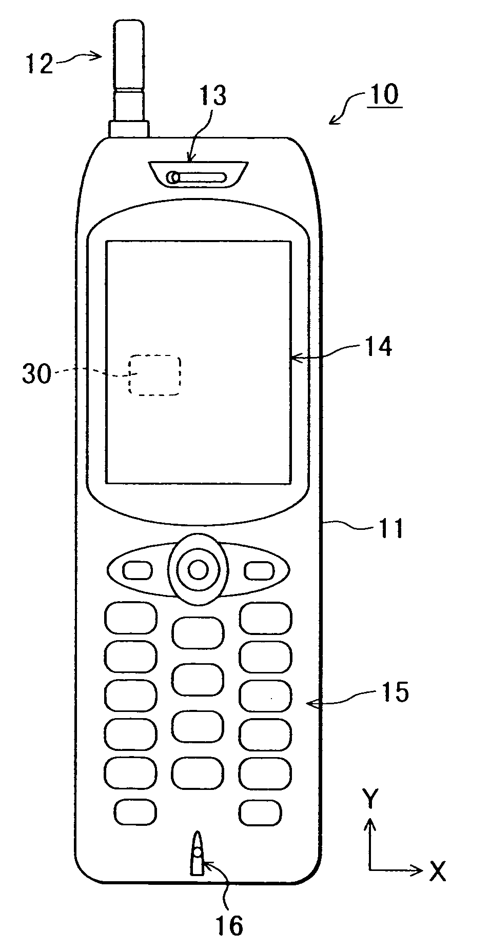
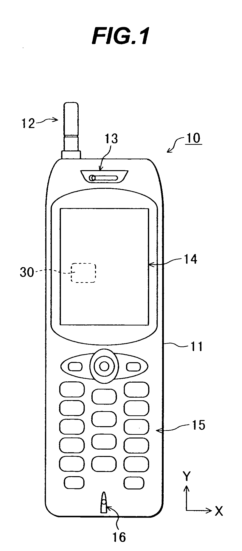
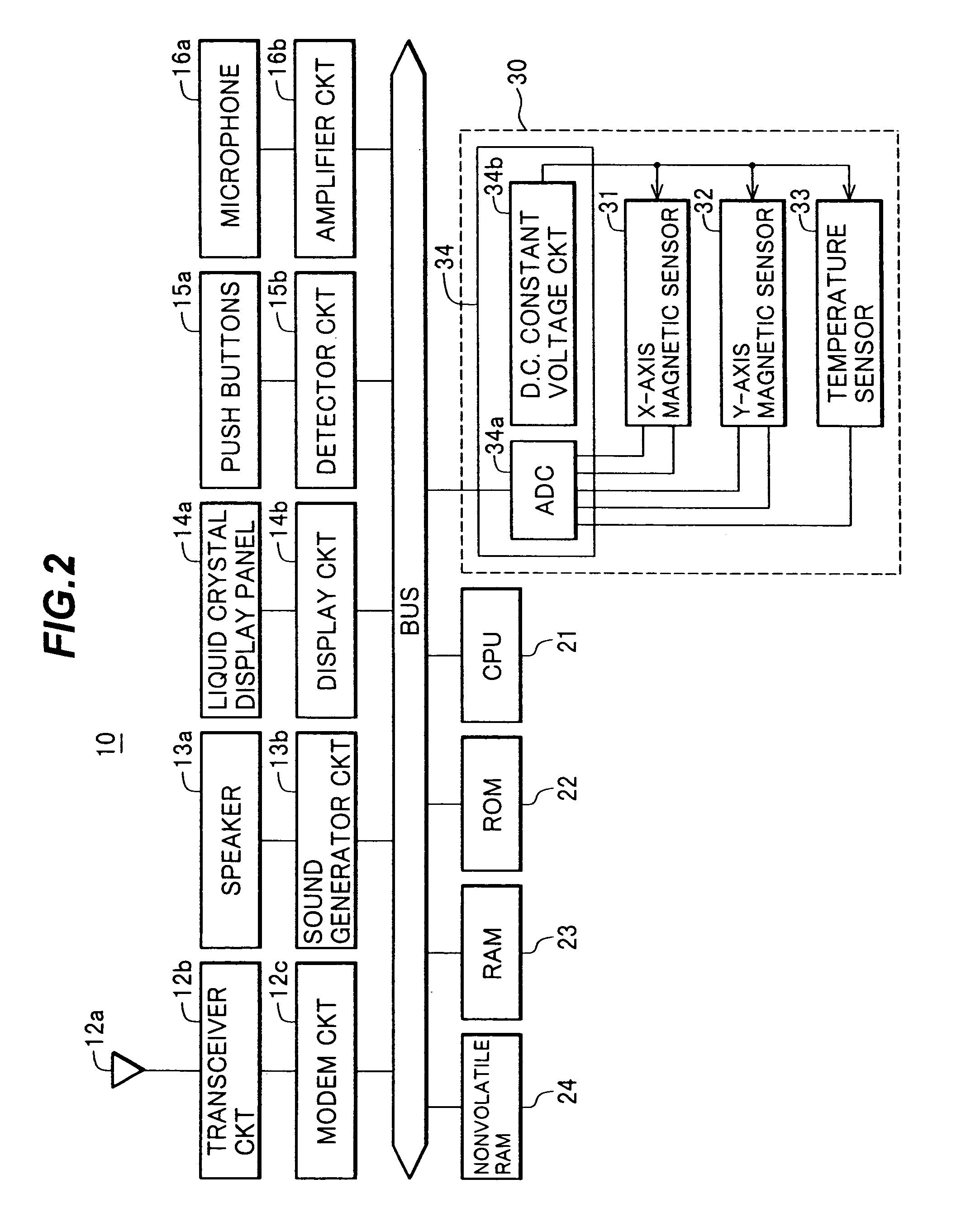
[0046] A portable electronic apparatus according to an embodiment of the invention will be described with reference to the accompanying drawings, by using a portable phone as an example of the portable electronic apparatus. As shown in the schematic plan view of FIG. 1, the portable phone 10 has a casing 11, an antenna unit 12, a speaker unit 13, a liquid crystal display unit 14, an operation unit (operation signal input unit) 15 and a microphone unit 16. The casing 11 is generally rectangular having sides extending along orthogonal X- and Y-axes as viewed in plan in FIG. 1. The antenna unit 12 is disposed at the upper right or left side of the casing 11. The speaker unit 13 is disposed at the uppermost front side of the casing 11. The liquid crystal display unit 14 is disposed at the front side of the casing 11 under the speaker unit 13. The liquid crystal display unit 14 is used for displaying characters and graphic. The operation unit 15 is disposed at the front side of the casin...


PUM


Abstract

A portable phone has a CPU and a magnetic sensor unit including an X-axis magnetic sensor, a Y-axis magnetic sensor, and a temperature sensor. CPU measures at first and second temperatures the influence of a magnetic field of permanent magnets upon an output Sx of the X-axis magnetic sensor and an output Sy of the Y-axis magnetic sensor, and stores the influence data together with the first and second temperature data. CPU estimates at the present temperature the influence upon the output Sx of the X-axis magnetic sensor and the output Sy of the Y-axis magnetic sensor, from the present temperature detected with the temperature sensor and the stored influence data. CPU corrects the outputs Sx and Sy in accordance with the estimated influence and determines the direction of the portable phone from the corrected outputs Sx and Sy.

Description

CROSS REFERENCE TO RELATED APPLICATION [0001] This application is a Divisional of U.S. patent application Ser. No. 10 / 190,525 filed on Jul. 9, 2002.[0002] This application is based on Japanese Patent Application No. 2002-115250, filed on Apr. 17, 2002, the entire contents of which are incorporated herein by reference. BACKGROUND OF THE INVENTION [0003] A) Field of the Invention [0004] The present invention relates to a portable electronic apparatus having a communication device with permanent magnets and a direction (azimuth) measuring device, to a magnetic sensor unit suitable for the apparatus, and to a direction measuring method for the apparatus. [0005] B) Description of the Related Art [0006] A magnetic sensor unit is known which detects geomagnetism and measures a direction. Recent studies are directed to adding a navigation function to a portable electronic apparatus typically a portable phone having the communication device and the magnetic sensor unit capable of detecting g...

Claims


Application Information

Patent Timeline
IPC IPC(8): H04B1/40G01B7/00G01B7/30G01C17/28G01C17/38H04M1/21H04M1/72403
CPCG01C17/28G01C17/38H04M2250/12H04M1/72522H04M1/21H04M1/72403H04B1/40
Inventor SATO, HIDEKI
Owner SATO HIDEKI
Learn More