Door frame

a door frame and frame technology, applied in the field of door frames, can solve the problems of increased weight, cost, and man-hours

Inactive Publication Date: 2005-05-19
AISIN SEIKI KK
View PDF9 Cites 12 Cited by
  • Summary
  • Abstract
  • Description
  • Claims
  • Application Information

AI Technical Summary

Benefits of technology

[0008] According to an aspect of the present invention, a door frame for a vehicle includes a lower frame for guiding an up / down movement of a window glass, a main frame connected to the lower frame for determining a top dead center of the window glass, and a bracket for attaching a door mirror secured to the lower frame and the main frame, the bracket having a bottom portion and a pair of opposing side wall portions extended from both sides of the bottom portion, and each having a thickness thicker than that of the bottom portion.

Problems solved by technology

However, these methods for increasing rigidity of the door frame causes increase of weight, cost, and man-hour.

Method used


Image

  • Door frame
  • Door frame
  • Door frame

Examples


first embodiment

[0020] the present invention will be explained with reference to the illustrations of the drawing figures as follows.

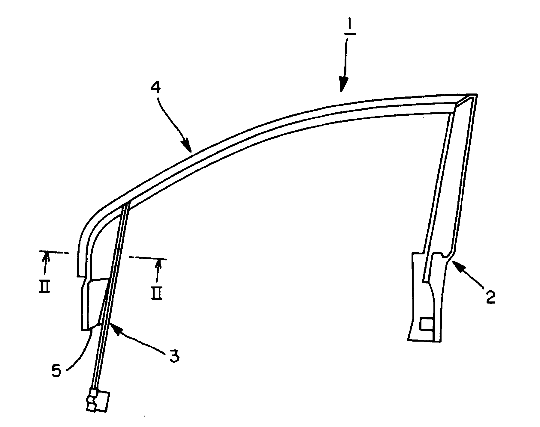
[0021] As shown in FIG. 1, a door frame 1 includes a center pillar 2 for guiding an up / down movement of a window glass and for making a vehicle to be locked / unlocked condition, a lower frame 3 provided apart from the center pillar 2, the lower frame 3 for guiding the up / down movement of the window glass, a main frame 4 for connecting the lower frame 3 to the center pillar 2 and for determining a top dead center of the window glass, and a bracket 5 for attaching a door mirror provided between a front end portion of the main frame 4 and the lower frame 3 and secured to both main and lower frames 4, 3.

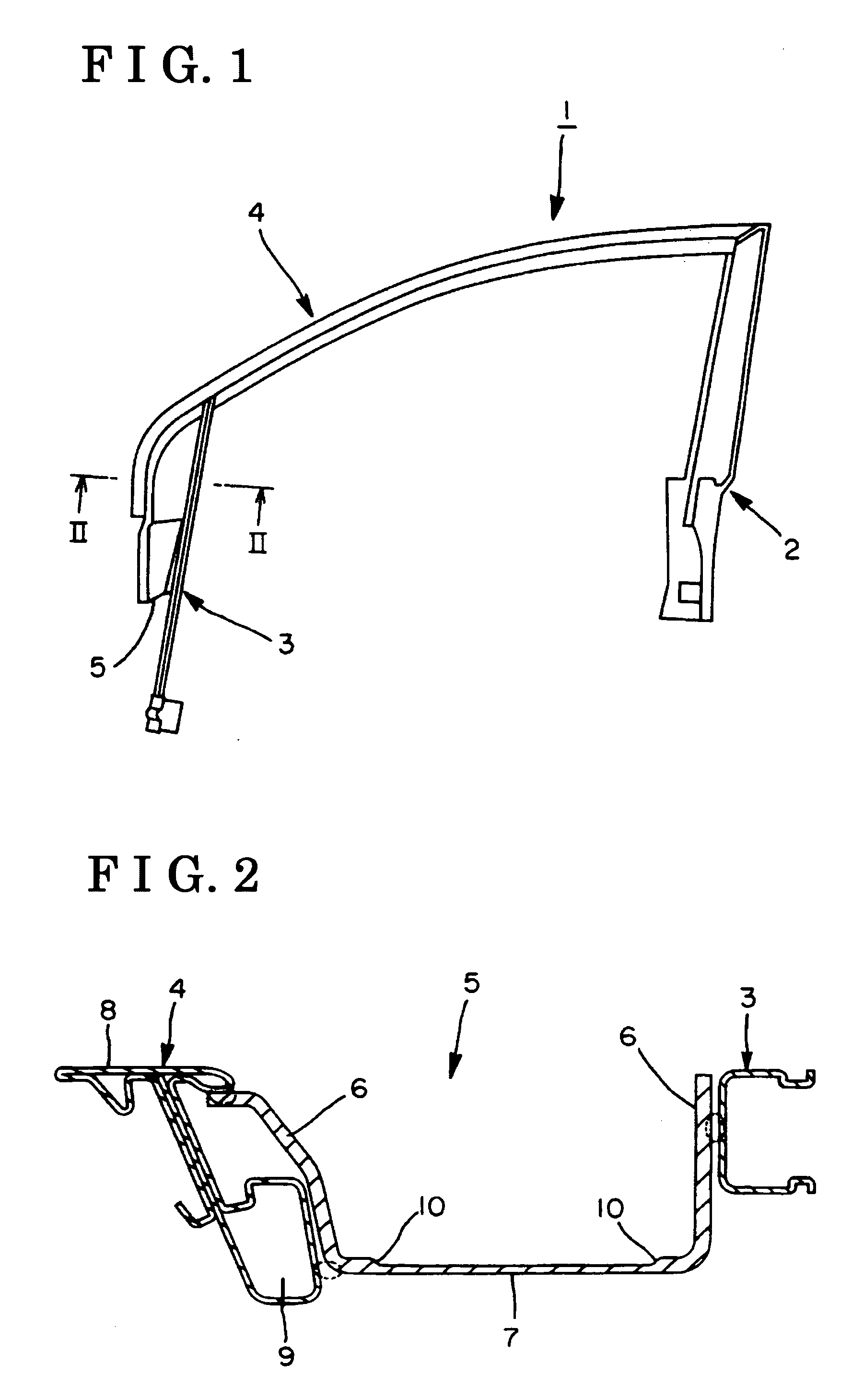
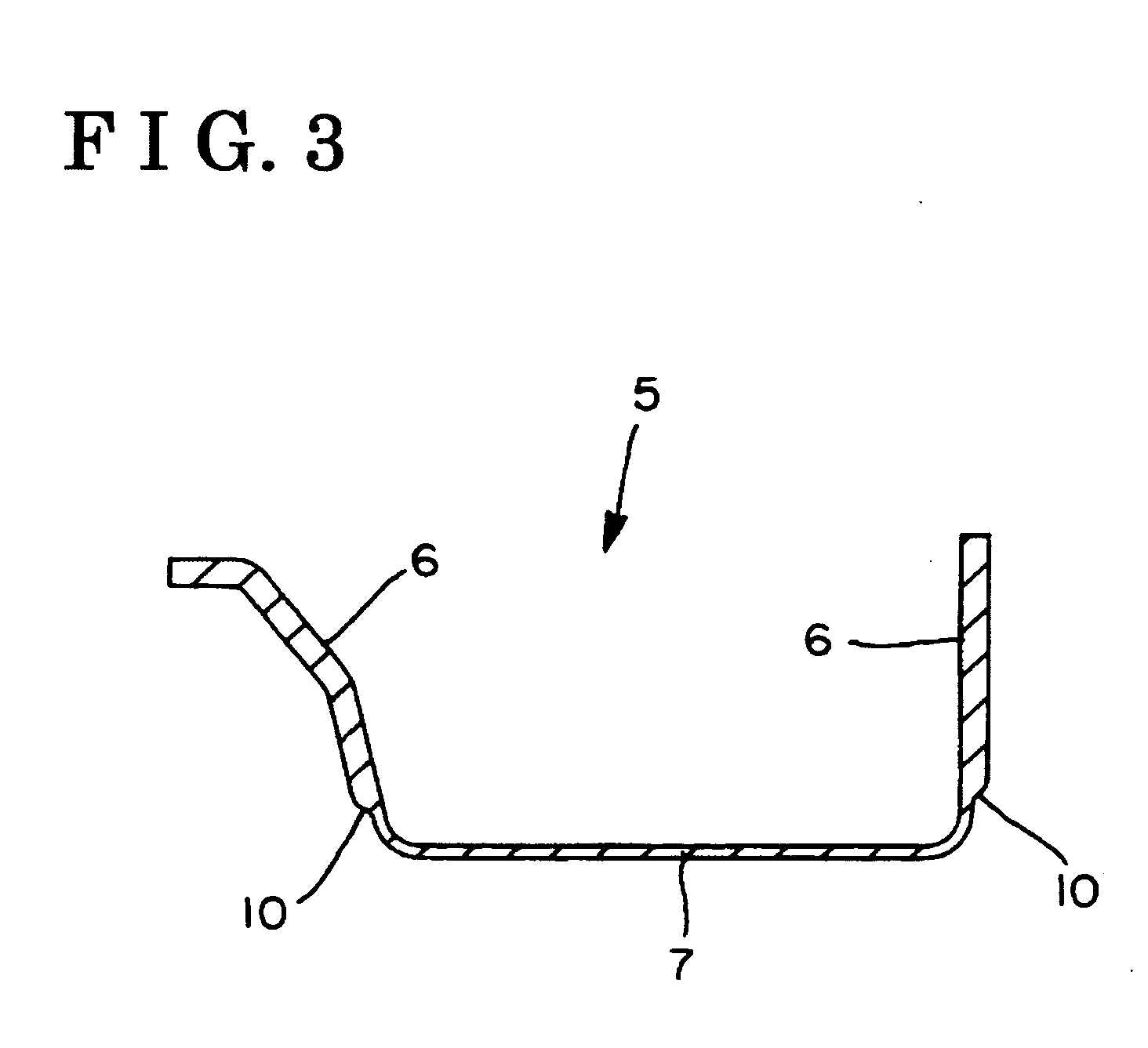
[0022] As shown in FIG. 2, the bracket 5 has an approximately U-shape cross-section. The bracket 5 is welded together with the lower frame 3 and the main frame 4. The bracket 5 includes a pair of opposing side wall portions 6 and a bottom portion 7. The bottom portion 7 of...

second embodiment

[0028] the present invention will be explained with reference to the illustrations of the drawing figures as follows.

[0029] As shown in FIG. 4, a door frame 1 includes a center pillar 2 and a lower frame 3 for guiding an open / close movement of a window glass, a main frame 4 for supporting the center pillar 2 and the lower frame 3 at apart position each other and for determining a top dead center of the window glass, and a bracket 5 secured to the main frame 4 and the lower frame 3. Preferably, the main frame 4 is made of, but not limited to, light alloy by extrusion. The main frame 4 may be made of steel, or the like.

[0030] To obtain the door frame 1 having increased rigidity without increase of weight, cost, and man-hour, the bracket 5 is made of light alloy by casting and includes ribs projecting in a vehicle width direction side by side. Light alloy includes aluminum alloy, magnesium alloy, and titanium series alloy, or the like.

[0031]FIG. 5 shows an example of the bracket 5 ma...


PUM


Abstract

A door frame for a vehicle includes a lower frame for guiding an up/down movement of a window glass, a main frame connected to the lower frame for determining a top dead center of the window glass, and a bracket for attaching a door mirror secured to the lower frame and the main frame, the bracket having a bottom portion and a pair of opposing side wall portions extended from both sides of the bottom portion, and each having a thickness thicker than that of the bottom portion.

Description

CROSS REFERENCE TO RELATED APPLICATIONS [0001] This application is based on and claims priority under 35 U.S.C. § 119 to Japanese Patent Application 2003-370794, filed on Oct. 30, 2003, and Japanese Patent Application 2003-370795, filed on Oct. 30, 2003, the entire content of which is incorporated herein by reference.FIELD OF THE INVENTION [0002] The present invention generally relates to a door frame. More particularly, the present invention relates to a door frame having a bracket for attaching a door mirror for a vehicle. BACKGROUND [0003] A door frame includes a center pillar for guiding an up / down movement of a window glass and for making a vehicle to be locked / unlocked condition, a lower frame provided apart from the center pillar, the lower frame for guiding the up / down movement of the window glass, a main frame for connecting the lower frame to the center pillar and for determining a top dead center of the window glass, and a bracket for attaching a door mirror, the bracket ...

Claims


Application Information

Patent Timeline
Patent Type & Authority Applications(United States)
IPC IPC(8): B60J1/17B60J5/04
CPCB60J1/17B60J5/0408B60J5/0406B60J5/0404
Inventor MASUNAGA, SATOSHIYAMASAKI, HIROAKI
Owner AISIN SEIKI KK
Why Eureka
Try Eureka