Eureka AIR delivers breakthrough ideas for toughest innovation challenges, trusted by R&D personnel around the world.

Fiber optic cable enclosure

a fiber optic cable and enclosure technology, applied in the direction of electrical apparatus casings/cabinets/drawers, lighting conductor installation, coupling device connection, etc., can solve the problems of not meeting the requirements of fixed parameters of these devices, all data and telecommunications transmission companies require backup systems, breakdowns are tantamount to catastrophes, etc., to achieve maximum internal volume

Inactive Publication Date: 2005-05-19
FULLER DENISE E +1
View PDF6 Cites 79 Cited by
  • Summary
  • Abstract
  • Description
  • Claims
  • Application Information

AI Technical Summary

Benefits of technology

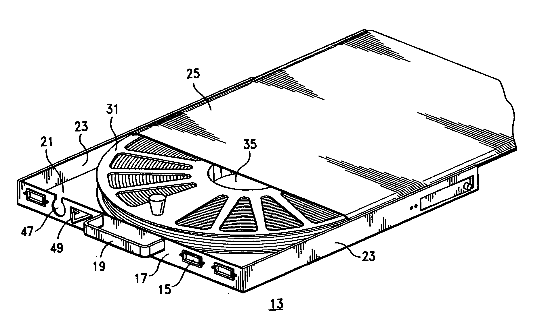
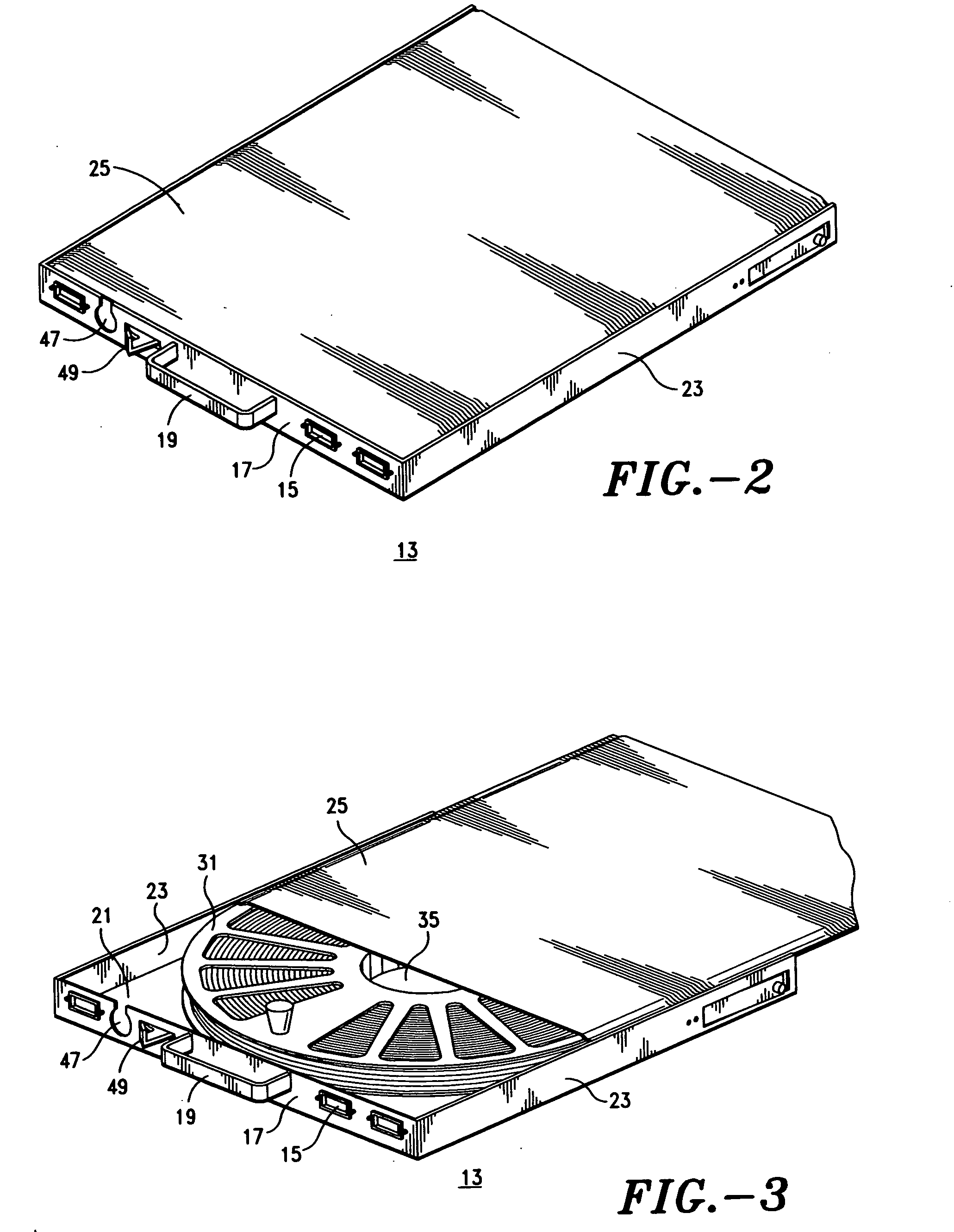
[0028] A cable reel is disposed for rotation in the enclosure with a vertical axis of rotation. The periphery thereof is positioned in close relation to at least the side panels thereof. The reel has a pair of horizontally oriented parallel side plates mounted on opposite sides of a central circular hub. The reel has a multiple of low-rise protuberances formed around the hub at least on the lower plate exterior surface of the reel. As a result, the reel rests in the enclosure on the bottom pan and rotates thereon on the protuberances. The clearance between the pan and the lower reel plate is minimal and considerably less than the diameter of the cable to be wound on the reel, and the width of the hub between the reel plates is maximized within the enclosure between the top surface plane of the box and the bottom pan. A predetermined length of fiber optic cable can be wound thereon without excess thereof being stored in the corners of the enclosure and without fracturing the internal fibers of the cable by being wound thereon with too acute of an angular bend around the hub.
[0038] It is a further object of the present invention to provide a cable reel enclosure which is comprised of a minimum of lightweight parts which is less expensive to manufacture and easier to install and does not need to have cable released from the corners thereof to extract the cable therefrom for response to emergency situations.
[0040] It is still a further object of the present invention to provide a cable enclosure which can fit through an aperture of a fixed width and height in sliding reciprocating relation and provide a maximum internal volume for a cable reel contained therein.
[0041] And it is yet another object of the present invention to provide an enclosure for a cable reel which has a brake on the reel during cable extraction which prevents the wound cable from loosening on the reel when extraction tension on the cable is released.

Problems solved by technology

However, despite the numerous designs, structures, and forms of the apparatus disclosed by and utilized in the prior art, which have been developed for the accomplishment of the specific objectives, purposes, and requirements of the adopted design criteria, for ready cable storage for emergency response and deployment, the devices, apparatus, and methods which have been heretofore devised and utilized to accomplish these goals consist basically of familiar, expected, and obvious combinations of configurations and arrangements of well-known apparatus which have substantial defects.
They do not meet the requirements of the fixed parameters for these devices for reliable and efficient operation.
Any breakdown is tantamount to a catastrophe, and as a result, all data and telecommunications transmission companies require backup systems.
An operations service center containing switching and server equipment is an especially vulnerable hub of the telecommunications network.
There are many problems with the present standardized design of the cable storage enclosures which were created initially to meet the design criteria.
The prior art enclosures containing a full complement of cable are very heavy.
The problem with using the standoff pins, which presumably was employed as the simplest or cheapest form of construction, is that if the cable is wound to tightly on the reel, the cable is bent sharply around each standoff pin, and that can cause fiber breakage in the fiber-optic cable.
Unfortunately, the lazy susan also allows the reel to continue turning after tension on the cable, utilized for pulling it off the reel, has ceased or abated thereby permitting the layers of cable to loosen within the reel.
No mechanisms have been designed for incorporation into the enclosures to cure this problem.
The side mounted drawer slides narrow the width of the drawer, and the height of the lazy susan in the drawer reduces the width of the reel which can be put in the drawer, whereby these devices occupy storage space in the allotted drawer space or volume, and the 50 m designated lengths of fiber optic cable cannot all fit onto the standard reels.
As a result, the cable cannot be quickly reeled from the front faceplate of the box as designed: the drawer must be slid out of the rack and opened to access the tied sections of cable, and release them, in order to extract the excess cable from the corners before the rest of the cable can be pulled off of the reel through the faceplate.
Thus, the enclosures do not function as designed.
Apart from the design problems, there are numerous operational problems which have become apparent which essentially are also design problems.
In addition to the lack of cable storage volume in the drawer, caused by the presence of the drawer slides and the lazy susan, the space between the peripheral edges of the reel and the sides of the enclosure has been such that the outer layer of cable will jam in between the reel sides and the enclosure side panels during rewinding because not all of the cable will fit on the reel.
This causes compression of the cable when the cable is wound too tightly onto the reel trapping it between the wound cable and the side panels and thereby possibly causing crushing and damage to the individual fibers.
As a heavy reel continues turning pass the point of jam, because angular momentum of the lazy susan allows continued rotation of the heavy reel, tension applied to the cable by pulling on it can jerk the cable out of the jam point and back bend the internal fibers in a direction opposite to its initial wind direction thus causing the back bend and possible fractures in the cable fibers.
The primary problem is that the design does not permit the storage drawers to function as intended.
More of a problem, however, is the fact that the cable tucked into the corners is subjected to severe bending which could cause the individual fibers in the fiber-optic cable to crack or fracture.
This is a severe operational defect which could render the cables partially if not wholly inoperative.
Making the drawers larger is not an option because the cabinet racks are existing installations in the facilities.
Likewise, storing less than the optimum 50 m length of 48 fiber cable on the reels renders the emergency design unusable.
Due to the play inherent in the bearings of the lazy susan, combined with an insufficient space for an adequate length of pin for positive engagement, the pin does not always engage both holes, thus preventing continuous positive lock up of the reel.
It also has the effect of crushing the cable and damaging the individual fibers.
Damage to the cable fibers occurs if one continues to forcefully wind the cable on the reel.
The roller guides are an expensive and unnecessary correction for a problem which should not exist.
The force required to rotate the reel is unnecessarily excessive, and there is no feedback to the operator or feel as to how tight the cable is being rewound onto the reel.
Thus, the cable can be caught on interfering surfaces and projections throughout the cable path during rewind.
In such circumstances, when the cable is snagged during rewind, and the operator continues the rewind process, a kink or excessive tension on the cable can cause damage to the cable.

Method used


Image

  • Fiber optic cable enclosure
  • Fiber optic cable enclosure
  • Fiber optic cable enclosure

Examples


Embodiment Construction

[0049] Reference is made to the drawings for a description of the preferred embodiment of the present invention wherein like reference numbers represent like elements on corresponding views.

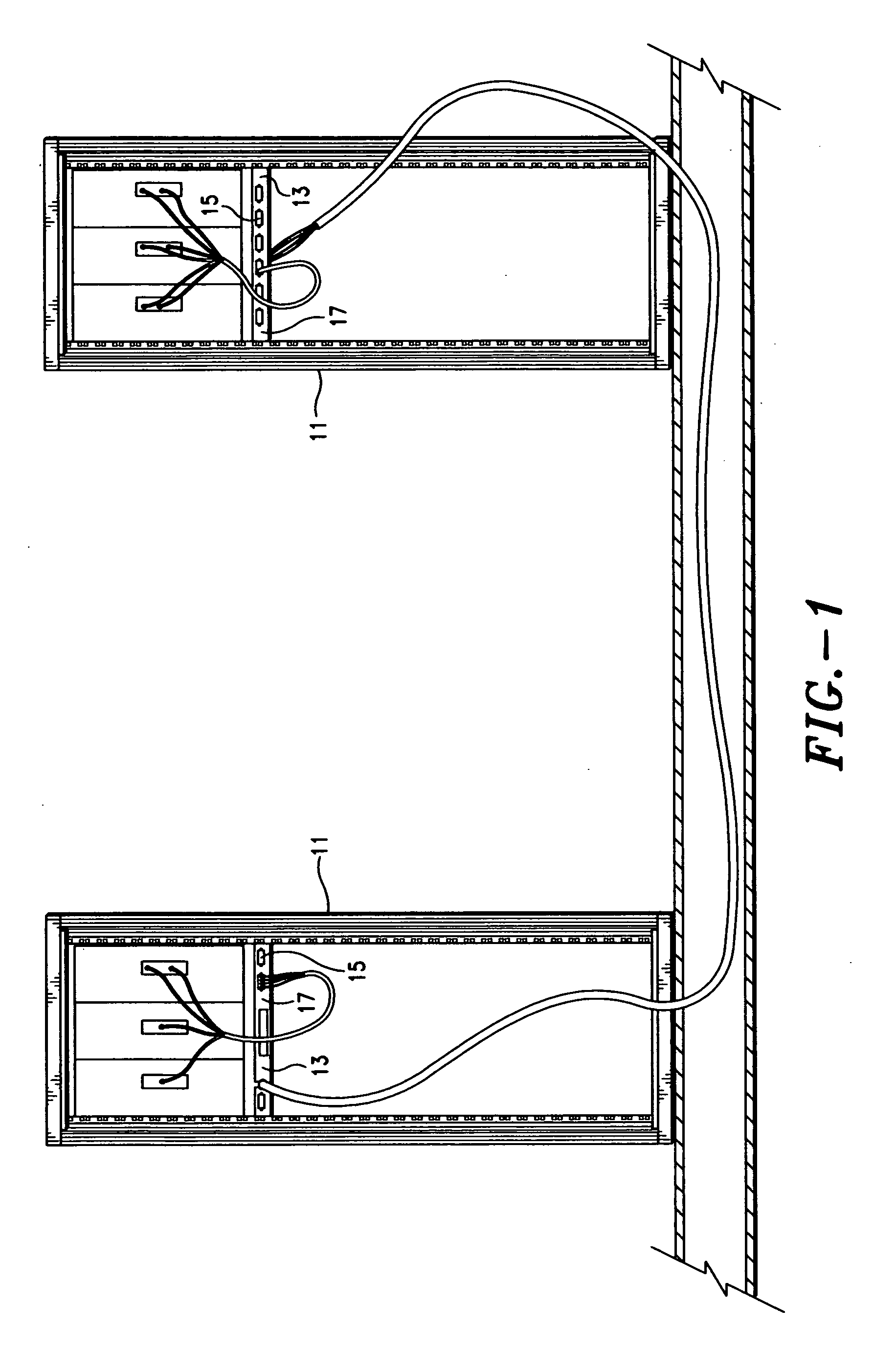
[0050]FIG. 1 shows a diagrammatic representation of the environment of the present invention which is a telecommunications and data transmission operations service center containing switching and server equipment.

[0051] Thereshown is a pair of cabinet racks 11 each containing a representative set of equipment. The present invention is a fiber optic cable enclosure 13 that is formed for providing the maximum internal volume therein for housing a cable storage reel in an enclosure which must fit in sliding horizontal reciprocating relation through or within an aperture having a fixed width and height formed in the front surface of a vertical rack. However, in actual operation, each of the racks contains a multiple of enclosures in a vertical stack. In a service facility, the spare cable enclosures...


PUM


Abstract

A fiber optic cable enclosure having a rectangular box with a sliding cover and containing a cable reel disposed and supported therein on protuberances projecting from the bottom of the reel with the side panels of the enclosure supported in C section channels for horizontal sliding intermittent reciprocating motion whereby a cable wound on said reel can be extracted and utilized as a jumper cable for establishing emergency connections in a telecommunications network.

Description

BACKGROUND OF THE INVENTION [0001] 1. Field of the Invention [0002] The present invention relates to an apparatus for storing data and telecommunication cables in storage cabinets for emergency deployment. Data and telecommunication transmission apparatus includes, among other things, hardwire or fiber optic cable transmission lines for transmitting electronic signals in a data stream. Hereafter, the use of the term telecommunications in this specification includes data transmission over the same signal transmitting infrastructure. [0003] More particularly, the present invention relates to an enclosure or case for the storage of predetermined lengths of fiber optic telecommunication transmission cable on reels with connectors at the ends thereof so that the cables can be unreeled and patched together in an emergency to bypass either remotely or locally located inoperative equipment at a telecommunications switching center. [0004] Still more particularly, the present invention relate...

Claims


Application Information

Patent Timeline
Patent Type & Authority Applications(United States)
IPC IPC(8): G02B6/44H02G11/02
CPCG02B6/4453H02G11/02G02B6/4457
Inventor FULLER, DENISE E.VOLIVA, RICHARD D.
Owner FULLER DENISE E
Why Eureka
Eureka Blog
Learn More