Engine for vehicle

a technology for vehicles and engines, applied in the direction of machines/engines, machine supports, cycles, etc., can solve the problems of high cost of protective measures in this way, water temperature sensors are susceptible to flying debris or debris or foreign matter such as earth and sand, etc., to ensure the durability of water temperature sensors, reduce costs, and raise the layout position of water temperature sensors

Active Publication Date: 2010-03-04
HONDA MOTOR CO LTD
View PDF4 Cites 2 Cited by
  • Summary
  • Abstract
  • Description
  • Claims
  • Application Information

AI Technical Summary

Benefits of technology

[0013]According to an embodiment of the present invention, the water temperature sensor mounted to the head portion of the cylinder can detect the water temperature at a portion of the water jackets for the engine where temperature variations are comparatively large.
[0014]Moreover, since the water temperature sensor mounted to the head portion of the cylinder in the rising state is located at a high position of the engine, a collision on the sensor with debris or foreign matter such as flying stones, earth and sand, etc. coming from the lower side can be obviated as securely as possible. Further, since the water temperature sensor is disposed directly under the upstream end opening portion of the intake port, a collision on the sensor with debris or foreign matter coming from the upper side can be prevented by the throttle body connected to the upstream side of the intake port. Furthermore, since the head portion of the cylinder is provided with the left-right pair of hanger bosses opposed to each other with the water temperature sensor therebetween, the collision on the sensor with debris or foreign matter coming from the left or right outer side can be prevented by the hanger bosses and the engine hanger brackets firmly attached thereto. Thus, the collision on the water temperature sensor with debris or foreign matter flying from the surroundings can be obviated without arranging any protective cover for exclusive use. This can contribute to ensuring the durability of the water temperature sensor and to reducing the cost.
[0015]According to an embodiment of the present invention, the cutout-like counter sinking is formed at a lower portion of the intake tube portion so that a part of the mounting seat ranges into the lower portion of the intake tube portion. This ensures that a sufficiently broad mounting seat for fastening the water temperature sensor can be secured at the cylinder wall directly under the intake tube portion, which makes it possible to mount the water temperature sensor assuredly and to raise the layout position of the water temperature sensor as much as possible.
[0016]According to an embodiment of the present invention, the opening portions of the intake and exhaust ports into the combustion chamber are so laid out that they as a whole are somewhat deviated toward the side opposite to the side of the water temperature sensor, within the combustion chamber. As a result, the spacing between the opening potions of the intake port into the combustion chamber and the water temperature sensor is broadened, so that the internal volume of the water jacket arranged therebetween can be set large. Accordingly, cooling water in the water jacket can be prevented from stagnating around the water temperature sensor, and accurate detection of water temperature can be achieved.

Problems solved by technology

Therefore, particularly in off-road vehicles such as buggies designed mainly for operating in an all terrain vehicle mode, the water temperature sensor is susceptible to flying debris or debris or foreign matter such as earth and sand, flying stones, etc. during the operation of the vehicle.
However, it is expensive to take protective measures in this way.

Method used


Image

  • Engine for vehicle
  • Engine for vehicle
  • Engine for vehicle

Examples


Embodiment Construction

[0027]Now, a mode for carrying out the present invention will be described below, based on a preferred embodiment shown in the accompanying drawings.

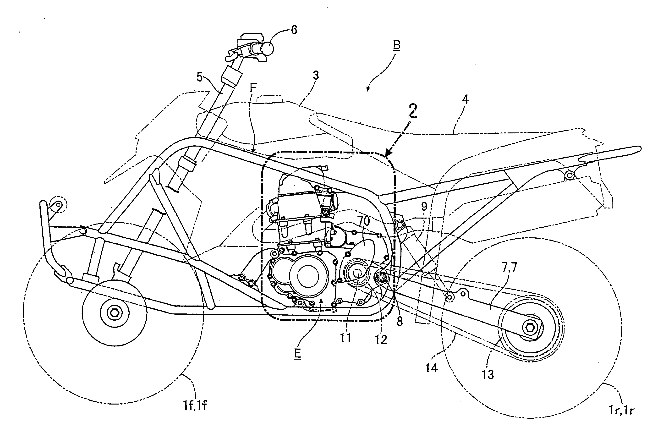
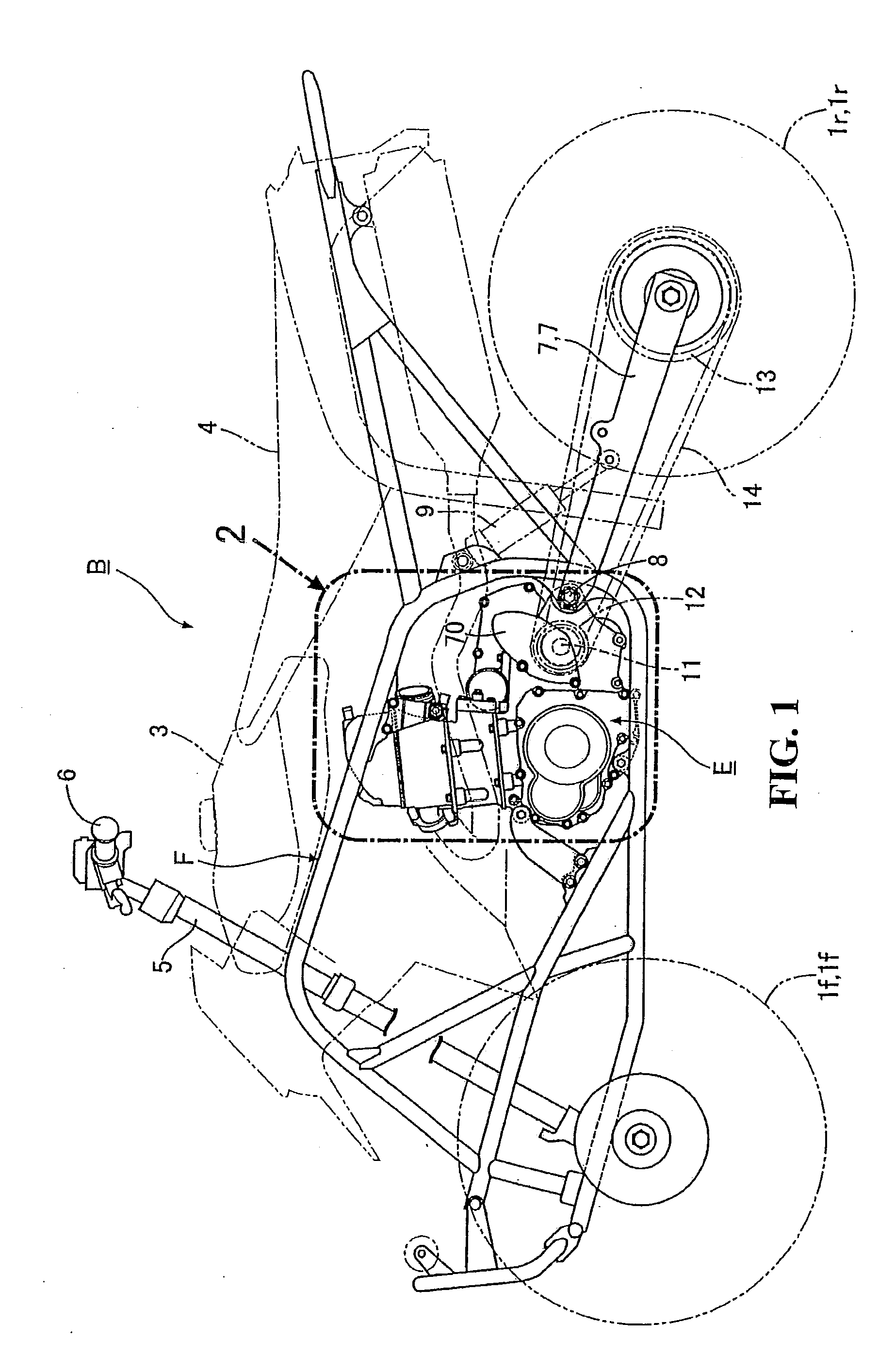
[0028]FIG. 1 illustrates a four-wheel buggy B configured as a saddle ride type vehicle in which a left-right pair of front wheels 1f, 1f are suspended from front portions of a body frame F, a left-right pair of rear wheels 1r, 1r are suspended on the rear side thereof and an engine E is mounted on a central portion of the body frame F, with its crankshaft 2 directed in the left-right direction of the vehicle. A fuel tank 3 is mounted to an upper front portion of the body frame F with a saddle 4 being mounted on the rear side thereof. In addition, a bar-type steering handle 6 for steering the front wheels 1f, 1f is rotatably supported on a head pipe 5 fixedly provided at a front end portion of the body frame F.

[0029]A left-right pair of rear forks 7, 7 are vertically swingably connected to the body frame F and the engine E through a pivo...


PUM


Abstract

A vehicle engine in which a water temperature sensor can be protected against debris or foreign matter such as earth and sand, flying stones, etc., from impacting the temperature sensor without taking any protective measure for exclusive use. A vehicle engine includes a head portion of the cylinder fitted with a water temperature sensor for detecting water temperature in a water jacket. The head portion of the cylinder is provided on one side thereof with a sensor mounting hole opening directly under an upstream end opening portion of an intake port. The water temperature sensor is mounted in the sensor mounting hole. Further, the head portion of the cylinder is formed with a left-right pair of hanger bosses which are opposed to each other, with the water temperature sensor therebetween. Engine hanger brackets extend from the body frame and are firmly attached to the hanger bosses.

Description

CROSS-REFERENCE TO RELATED APPLICATIONS[0001]The present application claims priority under 35 USC 119 to Japanese Patent Application No. 2008-225192 filed on Sep. 2, 2008 the entire contents of which are hereby incorporated by reference.BACKGROUND OF THE INVENTION[0002]1. Field of the Invention[0003]The present invention relates to a vehicle engine in which a cylinder is fitted with a water temperature sensor for detecting the temperature of water in a water jacket in the cylinder.[0004]2. Description of Background Art[0005]A vehicle engine is known, as disclosed, for example, in Japanese Patent Laid-Open No. 2003-112677 wherein the vehicle engine includes a water temperature sensor that is mounted to an upper surface of the cylinder which is disposed substantially horizontally, so that the distance from the ground surface to the water temperature sensor is comparatively short. Therefore, particularly in off-road vehicles such as buggies designed mainly for operating in an all terra...

Claims


Application Information

Patent Timeline
Patent Type & Authority Applications(United States)
IPC IPC(8): F02F1/10F02B67/00
CPCF01P11/16F01P2025/08F02B77/085F01P2050/16F02B61/02F01P2025/33
Inventor TAKI, MASAFUMI
Owner HONDA MOTOR CO LTD
Why Eureka
Try Eureka