Dual wall drill string assembly

a drill string and assembly technology, applied in the direction of directional drilling, borehole/well accessories, surveying, etc., can solve the problems of limiting the movement of drill pipe, affecting the formation of earth, and affecting the drilling effect, so as to increase the cutting volume, reduce the drilling difficulty, and reduce the drilling difficulty

Active Publication Date: 2005-05-19
AMERICAN AUGERS +1
View PDF22 Cites 114 Cited by
  • Summary
  • Abstract
  • Description
  • Claims
  • Application Information

AI Technical Summary

Benefits of technology

[0014] Accordingly, it is an advantage of the invention claimed herein to provide an apparatus that includes double-walled drill string pipe sections adapted for use in all subsurface drilling applications, it is another advantage of the invention to provide an apparatus having an inner tube adapted to bend to the arcuate path of a borehole with little or no resistance. It is also an advantage of the invention to provide an apparatus capable of conveying larger-sized cuttings and increased volumes of cuttings from the drilling mechanism to the surface of the ground. It is also an advantage of the invention to provide an apparatus that is capable of drilling in soft, medium or hard formations, permafrost formations, as well as corrosive formations with reduced negative environmental impact and reduced borehole wall damage. It is a further advantage of the invention to provide an apparatus that reduces or eliminates the risk of short circuiting the conductive wires on the drill string pipe sections. It is a still further advantage of the invention to provide an apparatus that permits an operator at the ground surface to know what rock or soil formation the drill is cutting and the location of the drill bit. It is also an advantage of the invention to electronically sense the hole pressures and differential pressures between the ID and OD at close proximity to the drill bit, as well as at other appropriate locations along the drill string length. It is another advantage of the invention to provide an apparatus that can detect the presence of hazardous gas, such as H2S. It is another advantage of the invention to provide an apparatus that produces a more efficient drilling mechanism by decreasing the incidence of “fracing out” of the subsurface formation. It is yet another advantage of the invention to provide an apparatus that achieves longer pilot borehole distances and has a longer lifespan in the borehole. It is a further advantage of the invention to provide an apparatus that is more easily assembled and performs all subsurface drilling more efficiently, more quickly, and less costly. It is a still further advantage to have an electric motor(s) turn the drill bit instead of turning the drill pipe to limit or raise the fatigue life of the drill string. It is a still further advantage to be able to adjust the angle of the adjustable bent sub electrically, which can enable a bit, after drilling the hole with casing being installed simultaneously, to pull through the casing, leaving the casing in place. It is a still further advantage to have an electric motor(s) between the bit and bent sub, so in order to deviate on a planned path so as to optimize the drilling task. Another aspect of the invention is the provision of a coil tubing apparatus which utilizes a “tube within a tube” design to achieve the aforesaid advantages of dual wall drill pipe. Additional advantages of the invention will become apparent from an examination of the drawings and the ensuing description.
[0015] As used herein, the term “arcuate” refers to a curving, bending, turning, arching or other non-straight line, path or direction. As used herein, the term “arcuate path that is generally horizontal” refers to a borehole having an entry hole and a separate exit hole that are connected by a curved path. It is contemplated within the scope of the term “arcuate path that is generally horizontal” that the borehole may have a longer vertical component than its horizontal component.
[0016] As used herein, the term “conductive” means able to convey, transmit or otherwise communicate a signal and / or provide electrical current.
[0017] As used herein, the term “fluid” relates to a liquid, air, a gas, or a combination of liquid, gas, and / or air. The term “fluid” includes, without limitation, mixtures of solids and water, oils, other chemicals and the like.
[0018] As used herein, the term “signal” refers to a means for communication between a transmitter and a receiver. The term “signal” includes, without limitation, analog signals, digital signals, multiplexing signals, light signals and the like.
[0019] As used herein, the term “steerable” means the ability to follow the deviated path of a planned drilled hole.

Problems solved by technology

This method of drilling is controllable, but it is dangerous.
Further, when the returned drilling mud or fluids and cuttings pass along the drilled hole, the hole can become packed between the drill pipe and the hole from the cuttings, thereby limiting the movement of the drill pipe.
This technique, however, impacts the earth's formation, for example, by forming or opening cracks in the formations.
Typically, much, if not all of the additional mud flows into the cracks and / or produces additional cracks.
In addition, when the hole is close to the surface, the additional mud can seep or flow to the surface in a process known as “fracing out,” which raises environmental concerns.
Also it has been proven that low pressure gas wells are being abandoned because this process results in plugging and sealing off the avenue of producing natural gas.
The drill pipe typically used in reverse circulation drilling, however, is very stiff and difficult to steer and bend in a borehole.
Thus, its use is limited to relatively straight hole applications, and it is not typically used in deviated hole drilling applications, which are commonly used in the construction, oil and gas, and mining industries.
However, these wires are typically exposed and, therefore, are vulnerable to damage from short circuiting and breakage during the drilling operation.

Method used


Image

  • Dual wall drill string assembly
  • Dual wall drill string assembly
  • Dual wall drill string assembly

Examples


Embodiment Construction

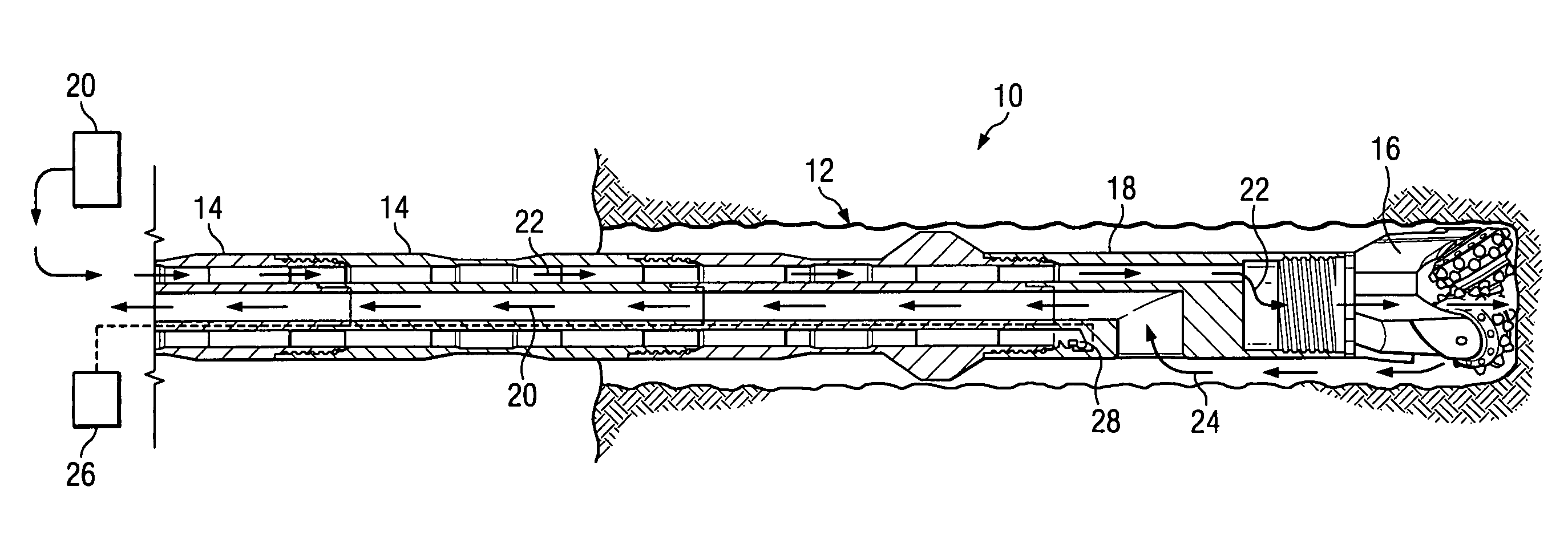
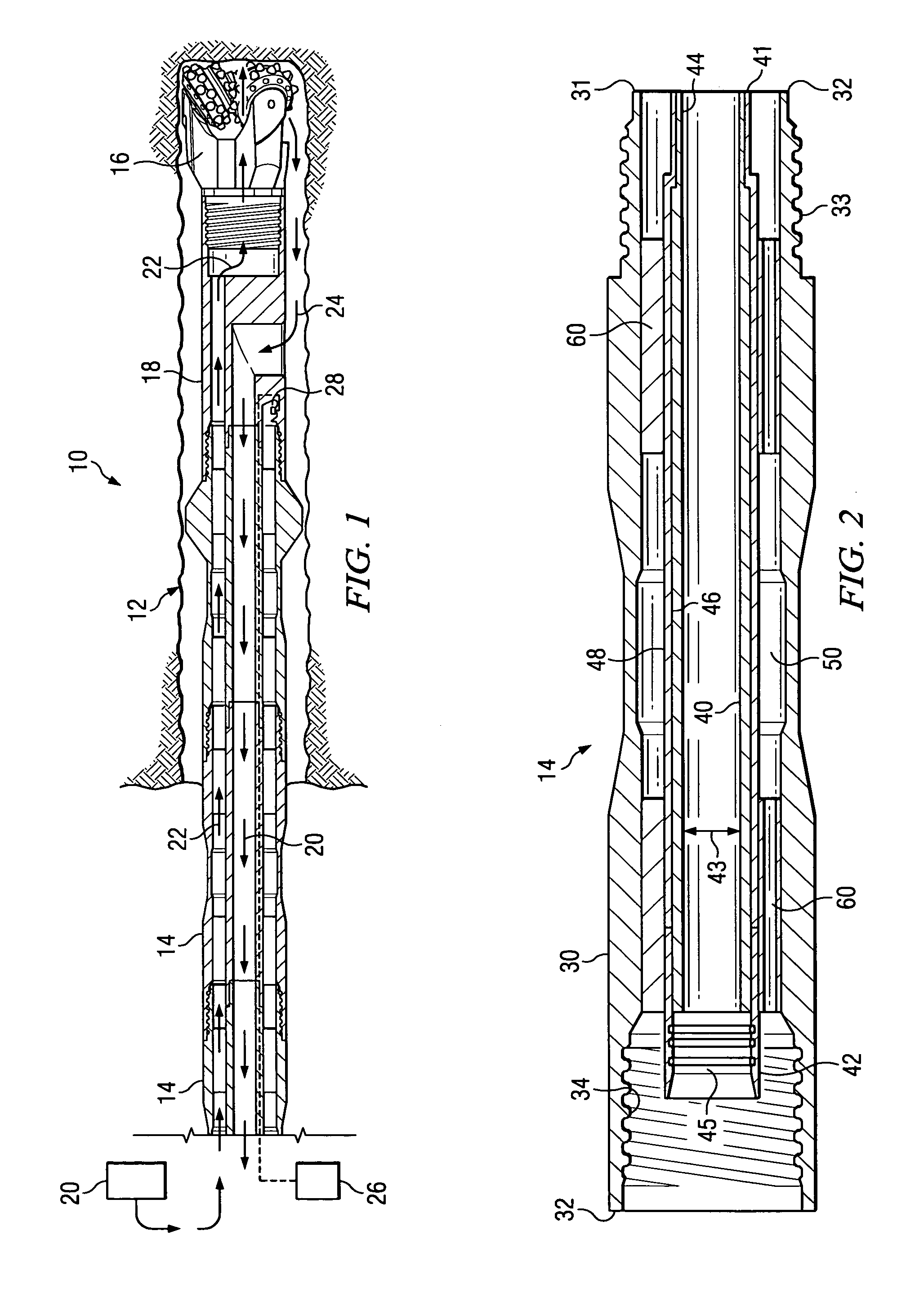
[0052] Referring now to the drawings, the various embodiments of the apparatus of the invention claimed herein are illustrated by FIGS. 1 through 18. FIG. 1 illustrates a preferred embodiment of the dual wall, jointed drill string assembly partially in a subsurface borehole. The preferred dual wall drill string assembly is designated generally by reference numeral 10 and the subsurface borehole is designated by reference numeral 12. As shown in FIG. 1, the preferred drill string assembly may comprise a plurality of dual wall pipe sections 14. It is contemplated, however, that the drill string assembly of the invention claimed herein may comprise a single dual wall pipe. The preferred drill string assembly may further comprise a drilling mechanism, an interchange sub, a means for conveying fluid under pressure, a signal source such as a transmitter or a source of electricity, a receiver, and a navigation transmitter as described in more detail below. It is further contemplated that t...


PUM


Abstract

A coil tubing or jointed dual wall drill string assembly for subsurface drilling. The drill string assembly includes a metallic outer tube having an outer tube first end and an outer tube second end opposite the outer tube first end. The assembly also includes a flexible, substantially non-metallic inner tube that is substantially enclosed within and generally coaxially aligned with the outer tube. The flexible, substantially non-metallic inner tube has an inner tube first end, an inner tube second end opposite the inner tube first end, and an inner tube inner diameter. The inner tube and the outer tube define an annular channel therebetween. The drill string assembly also includes a means for conveying fluid through the annular channel toward the inner tube first end. The annular channel is adapted to convey drilling fluid under pressure toward the inner tube first end and the inner tube is adapted to convey cuttings toward the inner tube second end.

Description

CROSS REFERENCE TO RELATED APPLICATIONS [0001] The present application is a continuation-in-part of attorney docket number 1471107-0202, Ser. No. 10 / 712,324, filed Nov. 13, 2003, entitled “Dual Wall Drill String Assembly”, by William G. Riel and Kris L. Church.BACKGROUND OF THE INVENTION [0002] 1. Field of the Invention [0003] The present invention relates generally to drill string assemblies. More particularly, the invention relates to a dual wall drill string assembly for use in subsurface drilling applications. [0004] 2. Background and Description of the Prior Art [0005] Drill pipe is used in various ways and for different applications including mining for precious gems, precious metals or coal; installing public and private utilities; drilling for oil and various gases including coal methane; creating an avenue to link the surface to one or more reservoirs; and linking a location on the surface or the subsurface with another surface or subsurface location. Accordingly, drill pip...

Claims


Application Information

Patent Timeline
Patent Type & Authority Applications(United States)
IPC IPC(8): E21B7/06E21B17/00E21B17/18E21B17/20E21B47/06
CPCE21B7/068E21B17/003E21B47/06E21B17/203E21B17/206E21B17/18
Inventor CHURCH, KRIS L.RIEL, WILLIAM G.
Owner AMERICAN AUGERS
Why Eureka
Try Eureka