Drive power controller for hybrid vehicle

Active Publication Date: 2005-05-19
SUBARU CORP
View PDF12 Cites 46 Cited by
  • Summary
  • Abstract
  • Description
  • Claims
  • Application Information

AI Technical Summary

Benefits of technology

[0045] According to the drive power controller in the fifteenth aspect, when the hybrid vehicle is detected to be in under-steering conditions, the drive power control unit controls the motor generator coupled to the front wheels to add the regenerative braking power, and to improve the cornering ability of the inner wheel to allow the outer wheel to slip. Thus, the relative increase to the braking power is provided for cornering the inner wheel to add the yaw moment in the steering direction to the vehicle.
[0046] The drive power controller for the hybrid vehicle according to the present invention has the aforementioned features, thereby providing the following effects.
[0047] One of the effects is to enable the change in the torque distribution ratio between the front and rear wheels to be made in the wide range from the torque distribution for the front wheels being made too much thereof to the torque distribution of less than 5:5. Furthermore, the change in the torque distribution ratio between the front and rear wheels can be made freely irrespective of the speed difference between the front and rear wheels by the central differential. Thus, the active change in the torque distribution ratio between the fro

Problems solved by technology

However, it is not possible to continuously vary the torque distribution ratio from the ratio of 5:5 to more than that.
Accordingly, when an active change in the torque distribution ratio is positively attempted between the front and rear wheels on an assumption of various situations to improve running performance, there is a problem in which a limitation to the attempt may occur.
Furthermore, in the aforementioned prior art, the differential limiting clutch restricts differential rotations to make the change in the torque distribution ratio, thereby naturally causing a degradation in a differential function with the change in the torque distribution ratio.
That is, the prior art imposes a limitation that the torque distribution ratio cannot be actively changed in a case where the differential function is required.
A problem that the

Method used


Image

  • Drive power controller for hybrid vehicle
  • Drive power controller for hybrid vehicle
  • Drive power controller for hybrid vehicle

Examples


first embodiment

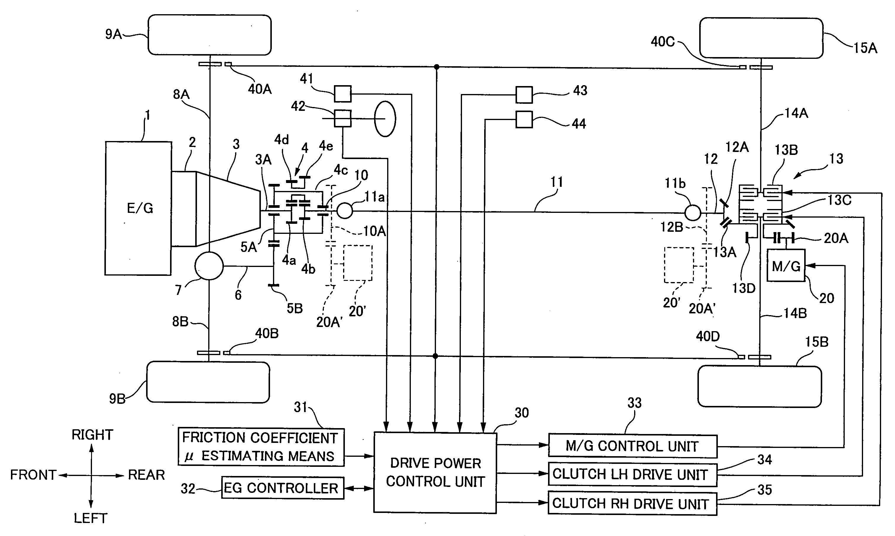
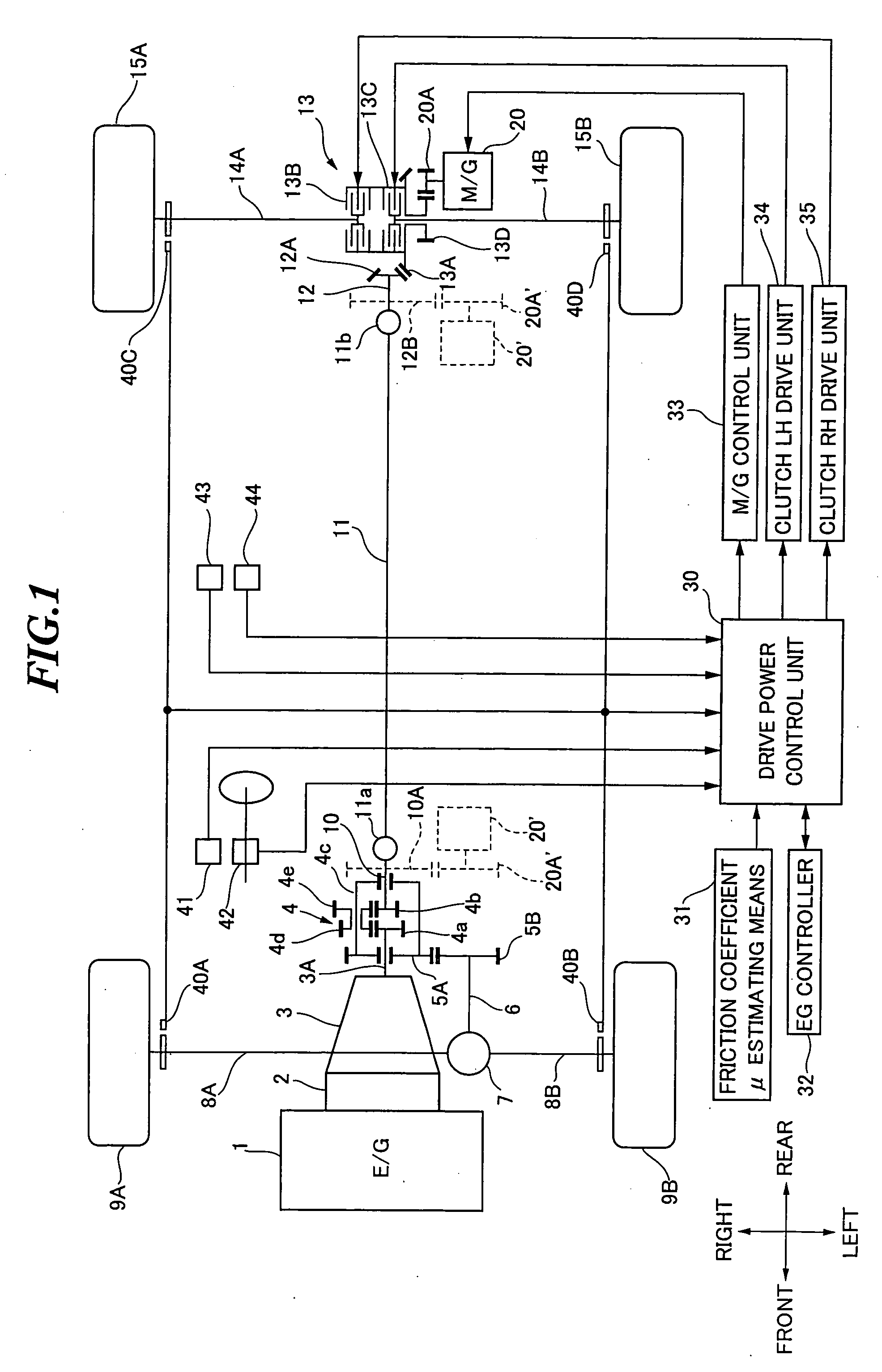
[0056]FIG. 1 is an explanatory view showing a system configuration according to a first embodiment.

[0057] Now, an explanation is given to the drive system of a vehicle, in which a power delivered from an engine 1 is supplied to a central differential 4 via an electromagnetic clutch 2 and a transmission 3. In the embodiment, the central differential 4 is a differential power transmission gear of a complex planetary gear train which includes a first sun gear 4a formed on a transmission output shaft 3A, a second sun gear 4b formed on a rear wheel drive shaft 10, and first and second pinions 4d and 4e held with a carrier 4c around the first and second sun gears 4a and 4b. The power supplied from the transmission output shaft 3A to the first sun gear 4a is transferred to the carrier 4c and the second sun gear 4b at a torque distribution ratio defined by gear dimensions of the aforementioned complex planetary gear train. The power is further transferred from the carrier 4c to a front whe...

second embodiment

[0089]FIG. 3 is an explanatory view showing a second embodiment according to the present invention. The embodiment uses the motor generator 20 coupled to the front wheel side drive system relative to the central differential 4. Additionally, the aforementioned twin clutch 13 is provided for the front right wheel drive shaft 8A and the front left wheel drive shaft 8B, while a rear wheel final reduction gear 16 is provided for the rear right wheel drive shaft 14A and the rear left wheel drive shaft 14B. The same components as those of the aforementioned first embodiment are indicated with the same symbols and will not be repeatedly explained.

[0090] In the second embodiment, the torque distribution ratio Tf0: Tr0 defined by the central differential 4 is set at that for the rear wheels being made too much thereof or for the rear wheels being provided a higher torque, e.g., front wheel ratio:rear wheel ratio=4:6. The additional torque from the motor generator 20 coupled to the front whe...


PUM


Abstract

A drive power from an engine is transferred to front wheel drive systems and rear wheel drive systems via a central differential. A torque distribution ratio between front and rear wheels defined by the central differential is set to one for the front wheels being made too much thereof, with a motor generator being coupled to the rear wheel drive systems. In response to detection signals from various sensors for detecting the running conditions, a drive power control unit controls the additional torque from the motor generator toward the drive torque or regenerative braking torque side, thereby changing the torque distribution ratio between the front and rear wheels. Thus, a degree of flexibility in making a change in the torque distribution between front and rear wheels or between right and left wheels is increased, thereby realizing an all-wheel drivable hybrid vehicle which provides further improved running performance.

Description

BACKGROUND OF THE PRESENT INVENTION [0001] The present invention relates to a drive power controller for a hybrid vehicle having a motor generator added to a drive system with an engine. [0002] The present application claims priority from Japanese Patent Application No. 2003-388155, the disclosure of which is incorporated herein by reference. [0003] Recently, in a background of environmental and energy-saving issues, attentions are being given to the hybrid vehicle having the motor generator added to the drive system with the engine. The hybrid vehicle of this type selectively couples the motor generator to the engine as a power source for the drive system, thereby providing various modes such as a running mode of using either or both of the engine and the motor generator, a power source braking mode of using either or both of the engine and the motor generator, and an energy regenerative mode of using the motor generator during braking operations. For the hybrid vehicle of this typ...

Claims


Application Information

Patent Timeline
IPC IPC(8): B60K6/26B60K6/36B60K6/365B60K6/387B60K6/40B60K6/48B60K6/52B60K6/54B60K17/04B60K17/16B60K17/346B60K17/35B60K17/356B60K23/04B60K23/08B60L7/16B60L15/20B60L50/16B60W10/00B60W10/02B60W10/04B60W10/06B60W10/08B60W10/12B60W10/14B60W10/18B60W20/00F16H48/10F16H48/22
CPCB60K6/48B60K6/52B60K23/04B60K23/0808B60T2270/613Y02T10/7258B60W30/02B60W30/18127B60W2550/148Y02T10/6221Y02T10/6265B60W10/08B60W2552/40Y02T10/62Y02T10/72B60W30/18145
Inventor MATSUNO, KOJI
Owner SUBARU CORP
Why Eureka
Try Eureka