
Illuminated membrane switch

a membrane switch and light technology, applied in the field of membrane switches, can solve the problems of increasing the complexity of the design process, changing the mechanical properties of the switch, and increasing the thickness of the switch, so as to achieve the effect of increasing the design flexibility in the illuminated region, high impedance detection circuitry, and increasing the resistance of materials

Active Publication Date: 2005-05-19
ILLINOIS TOOL WORKS INC
View PDF13 Cites 23 Cited by
  • Summary
  • Abstract
  • Description
  • Claims
  • Application Information

AI Technical Summary

Benefits of technology

[0008] The present invention provides an illuminated membrane switch that works with a variety of light sources while eliminating the problems of conductor shadowing, membrane switch thickness buildup, and area limitations in the graphically illuminated design. In the invention, the membrane switch conductors are fabricated from transparent conductor materials such as are commonly used in touch screens and the like. The higher resistance of these materials is moderated by the use of standard metallic conductors outside of the illuminated region and / or by the use of high impedance detection circuitry. A simple and compact illuminated membrane switch is created that allows for greater design flexibility in the illuminated region including, for example, an unbroken illuminated ring surrounding an illuminated character or symbol.
[0010] Thus it is an object of at least one embodiment of the invention to provide a simple backlit membrane switch.
[0016] Thus it is another object of at least one embodiment of the invention to permit complex illuminated symbols to be easily and flexibly created.
[0018] Thus it is another object of at least one embodiment of the invention to provide a separation between the graphics and the membrane switch for simplified manufacture and reuse of components.
[0026] It is another object of at least one embodiment of the invention to allow flexible selection of the light source.

Problems solved by technology

In this approach, the light conductive areas must be minimized so as to not unduly limit the available conducting surface of the contacts, and the graphics layer (which defines the light conducting areas of the button) and membrane switch must be designed in tandem, making the design process more expensive and cumbersome.
While this approach allows for some standardization of the membrane switch components, it increases the complexity of the membrane switch and may undesirably increase the thickness of the switch and change its mechanical properties.
This approach requires a relatively complex fabrication process and the use of an electroluminescent panel for the light source.

Method used


Image

  • Illuminated membrane switch
  • Illuminated membrane switch

Examples


Embodiment Construction

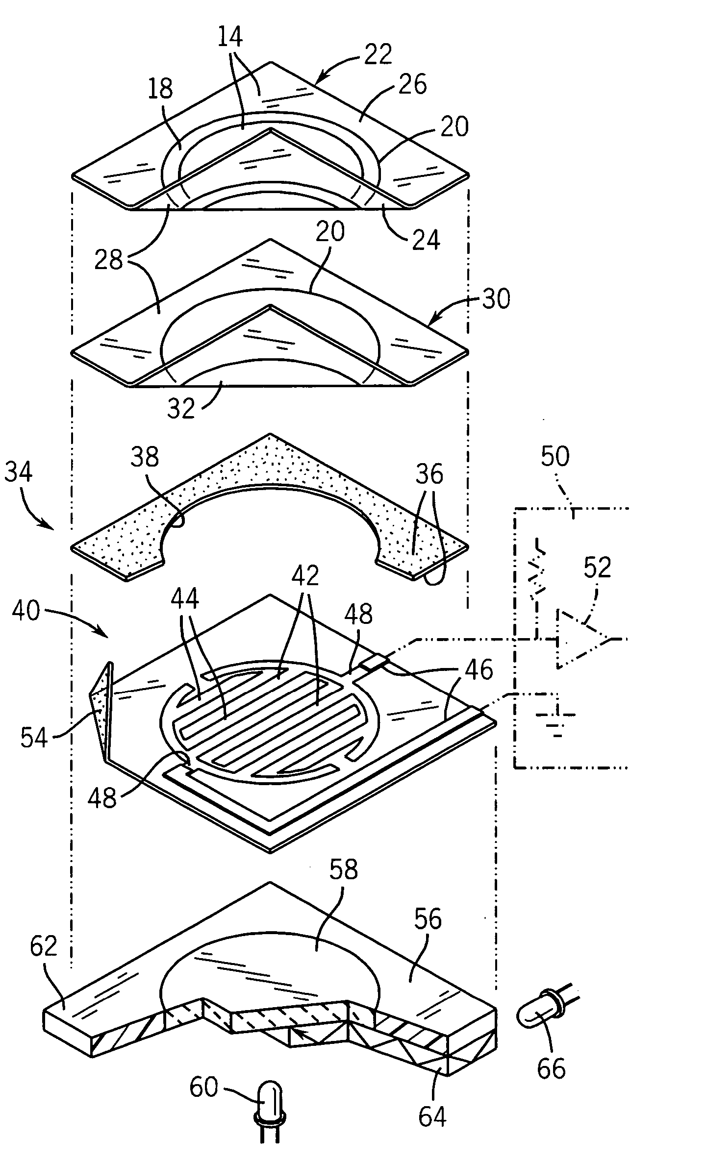
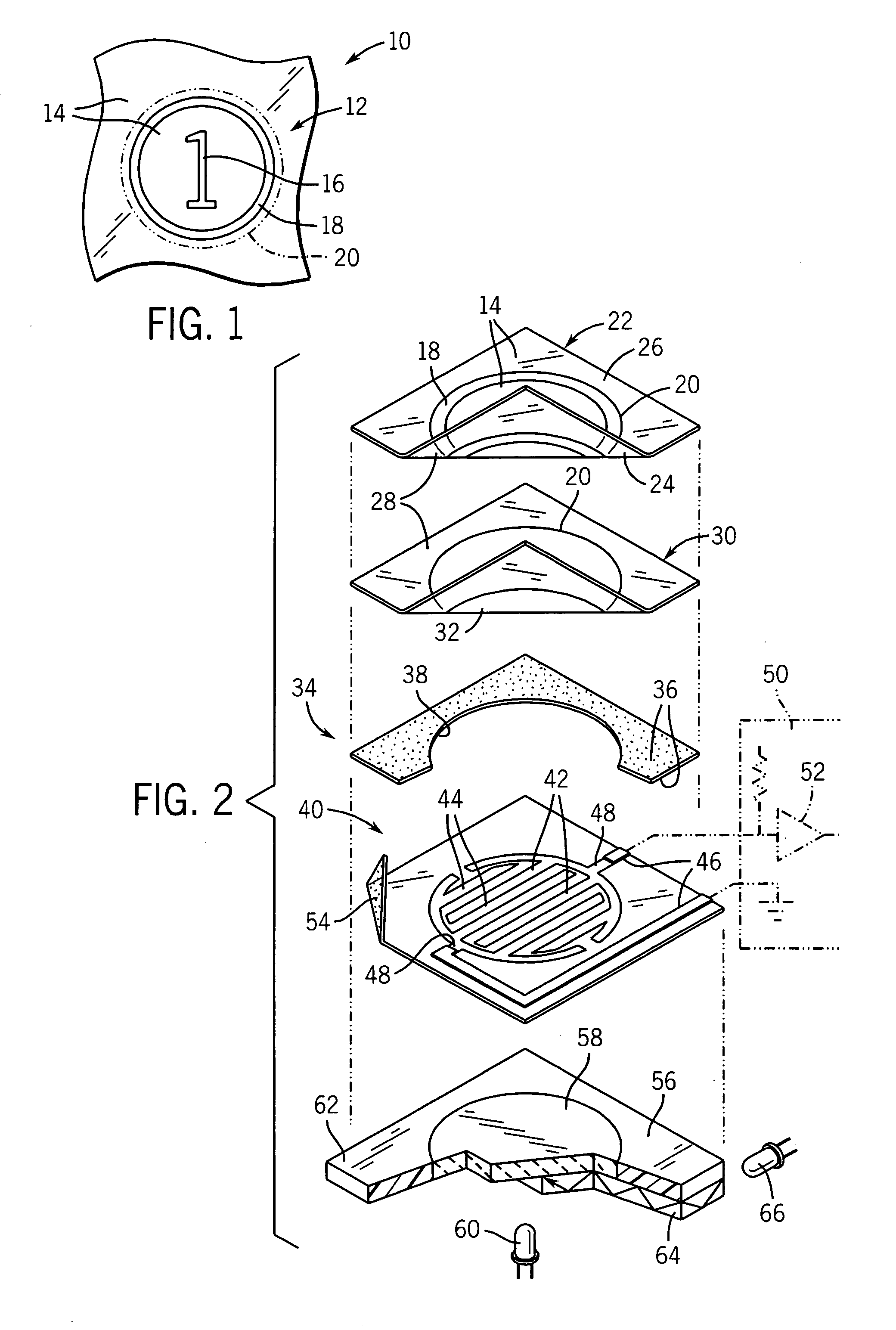
[0034] Referring now to FIG. 1, an illuminated membrane switch 10 of the present invention may provide for a graphic 12 to define a button area 20 and having printed opaque areas 14 selectively blocking the transmission of light to define an illuminated symbol 16 surrounded by an unbroken, illuminated ring 18. The graphic 12 thus defines a target to be pressed by a user to activate a particular membrane switch.

[0035] Referring also to FIG. 2, starting at an outer face toward the user, the illuminated membrane switch 10 includes a graphic layer 22 being a flexible, transparent polyester, polycarbonate, or other transparent sheet material well known in the art. The graphic layer 22 is printed on its rear, inner surface an opaque ink 24 such as creates the printed opaque areas 14. By printing on the rear side of the sheet of the graphic layer 22, the ink is protected from abrasion. Optionally, a textured ink 26 may be printed on the upper surface of the graphic layer 22 or it may be e...


PUM


Abstract

An illuminated membrane switch employs transparent conductive elements in the region of the button so as to provide passage of light from behind the membrane switch to the user without shadowing by opaque conductive elements.

Description

CROSS-REFERENCE TO RELATED APPLICATIONS [0001] This application claims the benefit of U.S. Provisional Application 60 / 520,476 filed Nov. 14, 2003, hereby incorporated by reference. STATEMENT REGARDING FEDERALLY SPONSORED RESEARCH OR DEVELOPMENT BACKGROUND OF THE INVENTION [0002] The present invention relates to membrane switches and in particular to a membrane switch providing for backlit, illuminated buttons. [0003] Membrane switches provide electrical contacts closing when a front flexible membrane is compressed by a finger touch or the like against a rear surface, typically a second membrane. Each of the membranes has electrical contacts printed on their opposing faces at button locations that are brought into electrical conduction when the membrane is flexed, and held apart by the natural elasticity of the membrane and a spacer layer when the front membrane is released. [0004] In some applications, it may be desirable to illuminate the membrane switch, for example, by backlighti...

Claims


Application Information

Patent Timeline
Patent Type & Authority Applications(United States)
IPC IPC(8): H01H13/785H01H13/83
CPCH01H13/785H01H13/83H01H2201/028H01H2229/028H01H2203/052H01H2221/002H01H2203/02
Inventor HOLSCHER, DAVID MATTHEW
Owner ILLINOIS TOOL WORKS INC
Learn More