System for stormwater environmental control

a technology for environmental control and stormwater, applied in water/sewage multi-stage treatment, liquid displacement, separation process, etc., can solve the problems of both limited methods and limited range of useful flow rates, and achieve the effect of convenient and effective cleaning in situ and more predictable operation

Active Publication Date: 2005-05-19
PARK ENVIRONMENTAL EQUIP LLC
View PDF95 Cites 32 Cited by
  • Summary
  • Abstract
  • Description
  • Claims
  • Application Information

AI Technical Summary

Benefits of technology

[0014] An advantage of the present invention is its ability to retrofit existing manholes.
[0015] The control structure may be designed to allow multiple connections to an array of inlet sources or treatment interceptor structures. The control structure can act as a stand-alone junction box.
[0016] The physical separation of control structure from treatment interceptor structure results in more predictable operation.
[0017] Independent sizing of the control structure may be guided by the customer's drainage pipe sizes, reflecting the anticipated maximum capacity of surge flow.
[0018] Independent sizing of the treatment interceptor structure and choice of filtering methods reflect the amount and type of anticipated waste pollutants needed to be captured.
[0019] A further object and advantage of the present invention is to introduce an environmental control system whereby the coalescing plate media do not have to be disassembled for their proper cleaning. With the present invention, the coalescing plate media are readily and effectively cleaned in situ.

Problems solved by technology

While both teachings of Cousino and Monteith provide a way to limit the kinetic energy in the separator area while at the same time allowing high flow to bypass the separator tank altogether, their methods are both limited to a certain range of useful flow rates and contaminant load.

Method used


Image

  • System for stormwater environmental control
  • System for stormwater environmental control
  • System for stormwater environmental control

Examples


Embodiment Construction

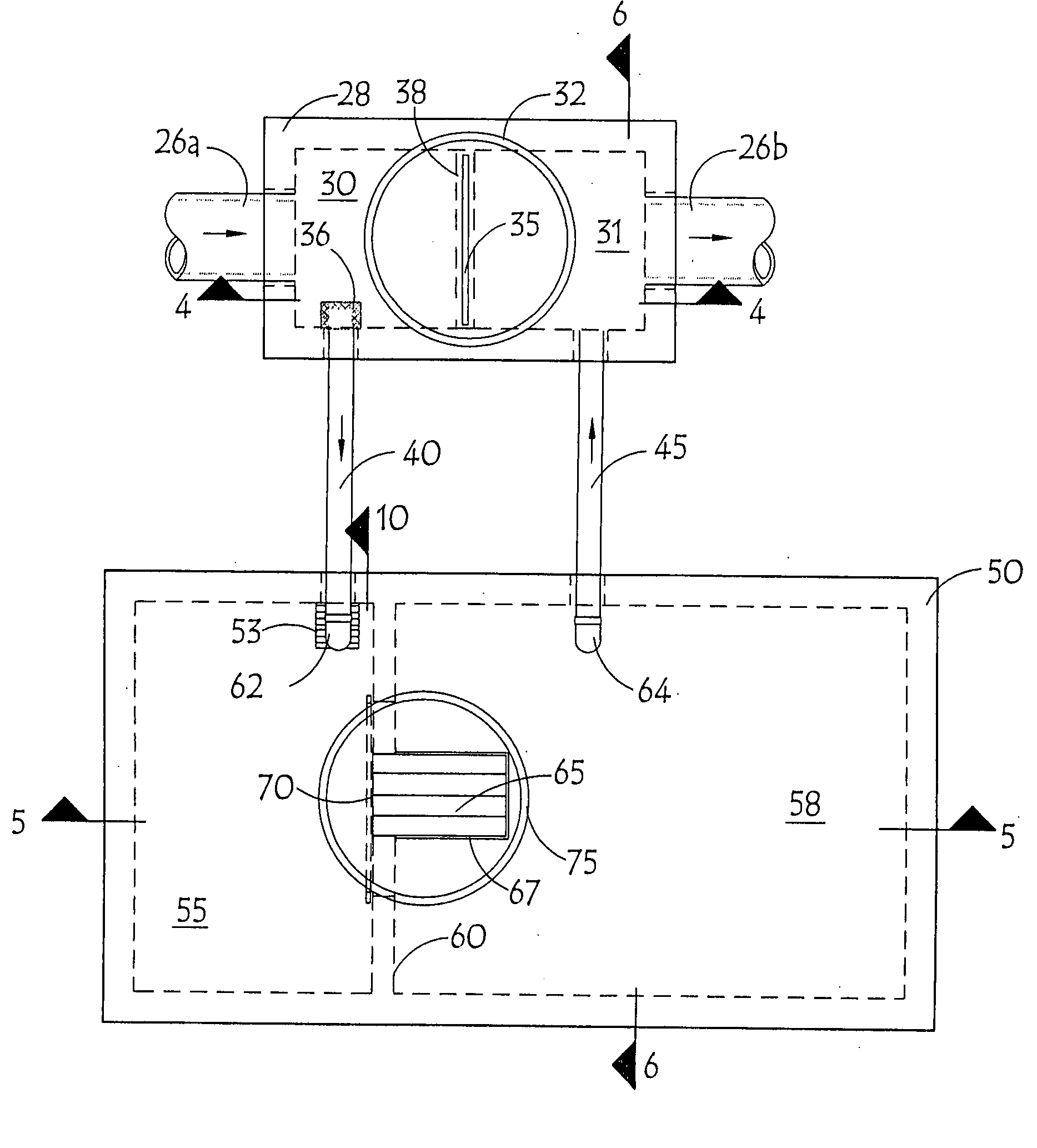
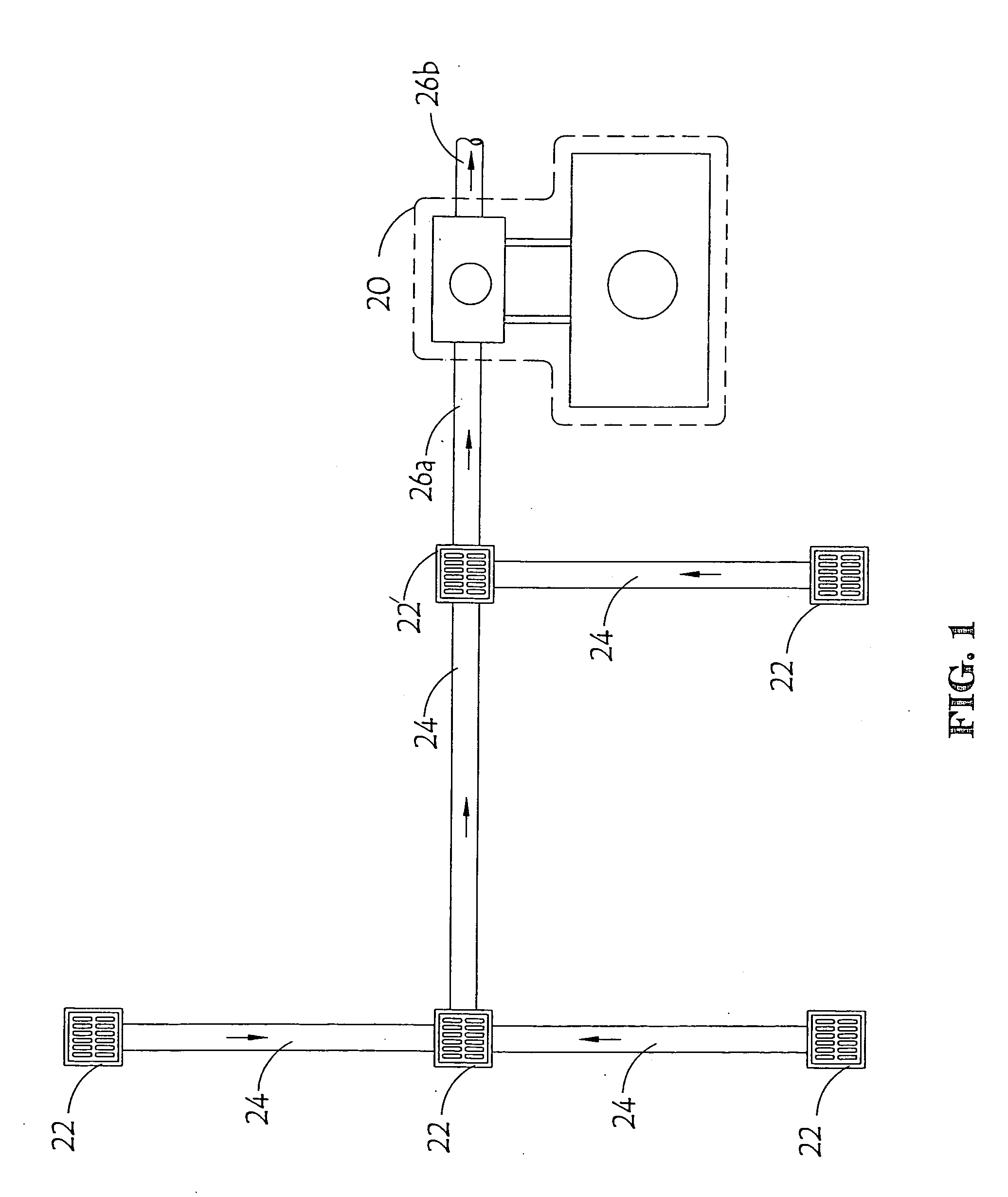
[0070]FIG. 1 shows a plan view showing the treatment system in the context of a typical application. Unprocessed fluids flow into one or more surface drain structures 22, which convey said unprocessed fluids to drain piping 24. A connection from a surface drain structure 22′ is made to the upstream convergence drain pipe 26a, conveying said unprocessed fluids towards a treatment system 20. Treatment system 20 provides for varying degrees of separation of contaminants, depending upon the flow conditions, resulting in a conversion of unprocessed fluid to processed fluid. The processed fluid then exits treatment system 20 by way of downstream convergence drain pipe 26b.

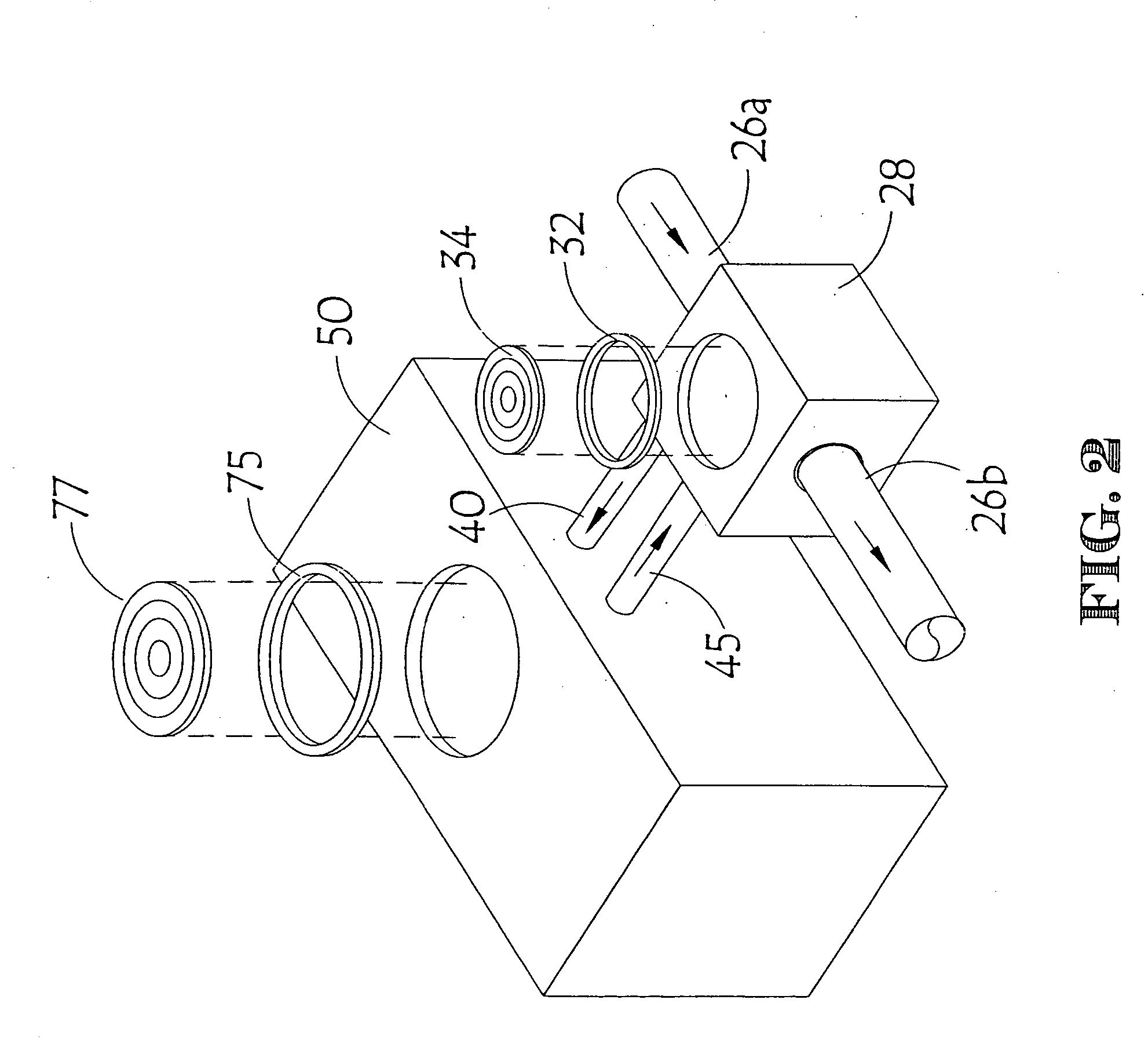
[0071]FIG. 2 shows a 3-D perspective view of the treatment system in a typical embodiment. Unprocessed fluid travels in upstream convergence drain pipe 26a, which is connected to control structure 28. Unprocessed fluid enters control structure 28. Control extension riser 32 is attached to the topside of control structur...


PUM

PropertyMeasurementUnit
control structureaaaaaaaaaa
intercepter structureaaaaaaaaaa
structureaaaaaaaaaa

Abstract

The present invention provides a method of installing an environmental control system so as to allow for separate sizing of treatment and bypass capacity while also offering the ability to make or change either treatment or bypass capacities at different times. This is accomplished by containing the treatment and bypass functions in separate chambers, using screen, baffle, or coalescing media pack to further refine effectiveness and capacity of each structure independently. The control structure and interceptor structure may be pre-engineered to a variety of sizes, capacities, or other specifications. This allows simple selection of a specific control structure and a specific interceptor structure from a variety of combinations, eliminating the need for custom engineering for each installation.

Description

REFERENCE [0001] Pursuant to 35 U.S.C. 119(e)(1), reference is hereby made to earlier filed provisional Patent Application No. 60 / 520,001 to Christopher N. Eberly for Improved System for Stormwater Environmental Control of filing date Sep. 14th, 2003.FIELD OF THE INVENTION [0002] The present invention relates generally to the environmental control of storm water and its associated contaminants. BACKGROUND OF THE INVENTION [0003] It is well known in the art that wastewater can be collected into a separator tank to remove debris. Separator tanks have long been used to separate oils from water. Generally, these debris or oils may be called contaminants. [0004] The use of separator tanks poses two problems when used to treat waste water. One, high flow rates create turbulence. The turbulence diminishes the ability of separator tanks to separate the contaminants. The turbulence may also re-mobilize the already separated contaminants, placing the contaminants back into the waste water to ...

Claims


Application Information

Patent Timeline
Patent Type & Authority Applications(United States)
IPC IPC(8): E03F5/16
CPCE03F5/16Y10T29/49826E03F2201/10
Inventor EBERLY, CHRISTOPHER N.
Owner PARK ENVIRONMENTAL EQUIP LLC
Why Eureka
Try Eureka