

Filter device
a filter device and filter technology, applied in the direction of moving filter element filters, filtration separation, separation processes, etc., can solve the problems of shortening the lifetime of the filter, affecting the filter, and affecting the filter performance, so as to prevent any agitation of the deposi
- Summary
- Abstract
- Description
- Claims
- Application Information
AI Technical Summary
Benefits of technology
Problems solved by technology
Method used
Image

Examples
first embodiment
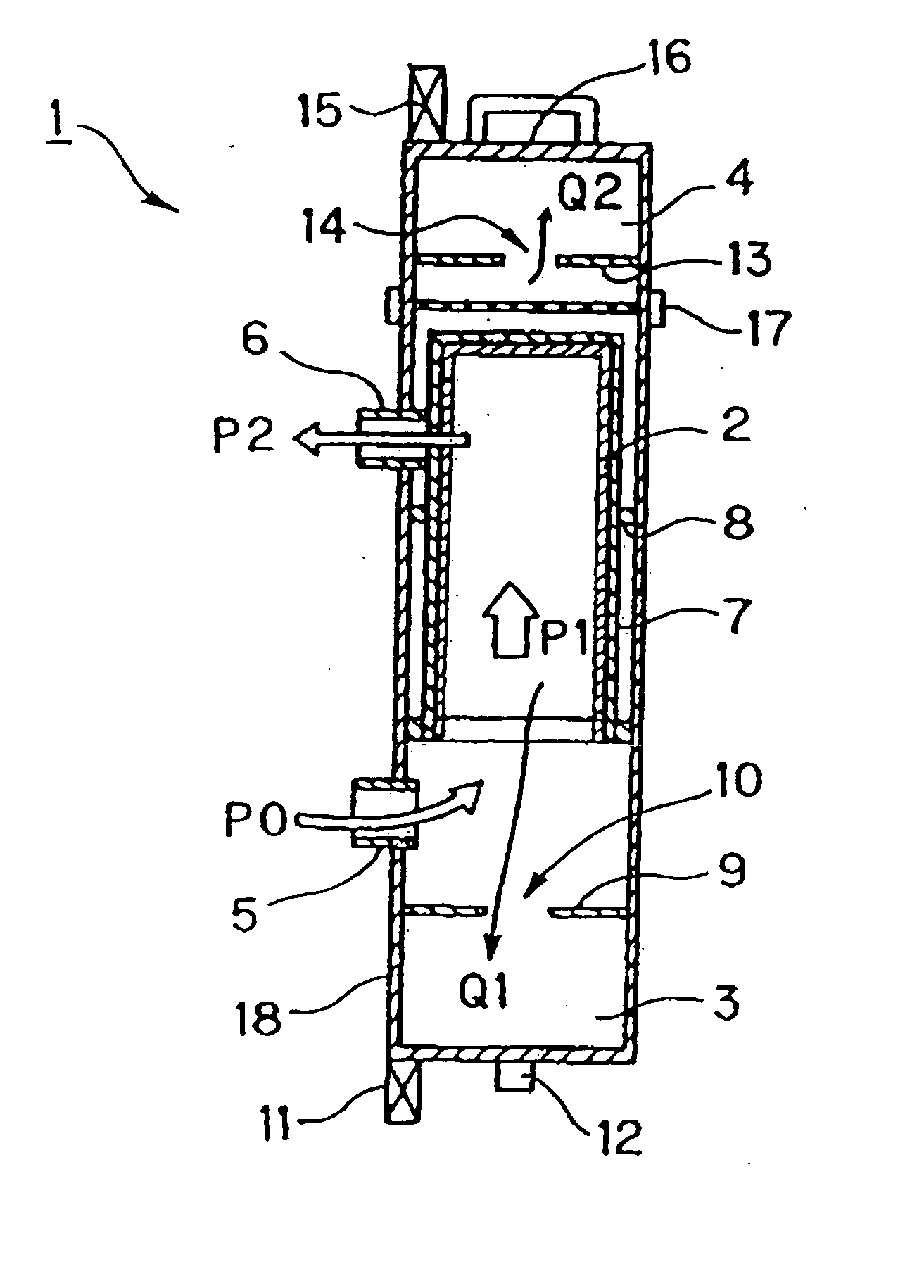
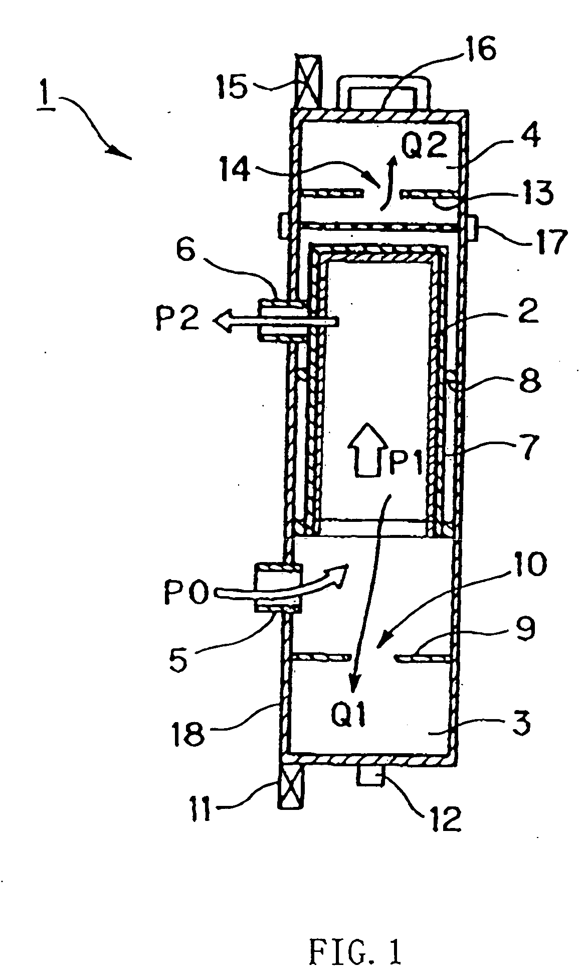
[0052] Referring to FIG. 1, explanation will be made on a filter device according to a first embodiment of the present invention. FIG. 1 is a cross-sectional view schematically showing the configuration of the filter device according to the first embodiment of the present invention.
[0053] As shown in FIG. 1, a filter housing 18 in a filter device 1 in the present embodiment comprises a container for accommodating a filter bag (a bag-like filter) 2, a deposit recovery tank 3 for recovering a deposit and a floating material recovery tank 4 for recovering a floating material.
[0054] The filter bag 2 is covered with a mesh-like bag filter bucket 7 made of metal or the like, and thus, is protected. Furthermore, the filter bag 2 is positioned by a filter presser 8 disposed at the filter housing 18. Moreover, the filter device 1 in the present embodiment is used in the state in which the opening of the bag-like filter bag 2 is oriented downward.
[0055] The deposit recovery tank 3 is locat...
example 1
[0074]FIG. 3 is a diagram illustrating the flow in a filter system to recycle the cleaning liquid.
[0075] In this filter system, a pump 40 is disposed downstream of a cleaning tank 30 containing the cleaning liquid therein, and further, a filter device 1 is disposed downstream of the pump 40.
[0076] The cleaning liquid contained inside of the cleaning tank 30 flows in a direction indicated by an arrow A by means of the pump 40. And then, the cleaning liquid flows in a direction indicated by an arrow B, and thus, flows into the filter device 1. As described above, by the filter device, the cleaning liquid is subjected to impurity separation by the filtration of the filter and separation of a component small in specific gravity by the specific gravity difference separation. Thereafter, cleaning liquid flows in a direction indicated by an arrow D, and thus, is returned to the cleaning tank 30.
[0077] Incidentally, recovered deposit is appropriately discharged in a direction indicated b...
example 2
[0078]FIG. 4 is a diagram illustrating the flow in a filter system to recycle the cleaning liquid.
[0079] In the filter system in this example, a hollow fiber membrane module (UF: ultrafiltration) 50 is disposed downstream of a filter device 1, unlike the system in Example 1. In this system, liquid filtered by the filter device 1 is further cross-flow filtered by the hollow fiber membrane module 50. Consequently, finer impurities can be removed. The cross-flow filtration by the hollow fiber membrane module 50 can suppress adhesion of particles and oil to a hollow-fiber membrane, thereby achieving a stable transmitted liquid flow rate. Liquid which cannot be filtered by the hollow fiber membrane module 50 is returned to the upstream side of a pump 40.
[0080] Incidentally, in this system, a condensed deposit and floating material are continuously recovered and discharged. Consequently, the cleaning liquid is allowed to steadily flow on a circulation path.
PUM
| Property | Measurement | Unit |
|---|---|---|
| specific gravity | aaaaa | aaaaa |
| specific gravity | aaaaa | aaaaa |
| flow rate | aaaaa | aaaaa |
Abstract
Description
Claims
Application Information