
Ice detection assembly installed on an aircraft

Inactive Publication Date: 2005-05-19
AUXITROL
View PDF9 Cites 24 Cited by
  • Summary
  • Abstract
  • Description
  • Claims
  • Application Information

AI Technical Summary

Benefits of technology

[0024] A fourth purpose of the invention is to implement successive icing / de-icing cycles on the detection assembly, such that de-icing is done more quickly.

Problems solved by technology

This can then lead to loss of lift and controllability of the aircraft.
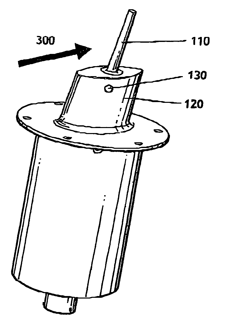
However, this type of detection assembly 100 has a major disadvantage for ice detection around the icing conditions (static temperature of the surrounding air near 0° C.).
Thus, when this OAT is equal to or slightly less than the icing temperature, the detection assembly according to prior art will not detect ice even if it is subjected to icing conditions.
However, this system does not enable a large reduction in the equilibrium temperature, and does not enable any control over the value of this resulting temperature reduction.
However, this ice detector 130 has a small detection area, and therefore ice detection may be not sufficiently reliable.
Furthermore, it only exposes a single detection face and does not extend in the three dimensions as the distance from the aircraft increases (as the said finger 110 does), which can reduce the quality of the result obtained.
Thus, the Peltier system is not adapted to fast de-icing to facilitate a new detection.

Method used


Image

  • Ice detection assembly installed on an aircraft
  • Ice detection assembly installed on an aircraft
  • Ice detection assembly installed on an aircraft

Examples


Embodiment Construction

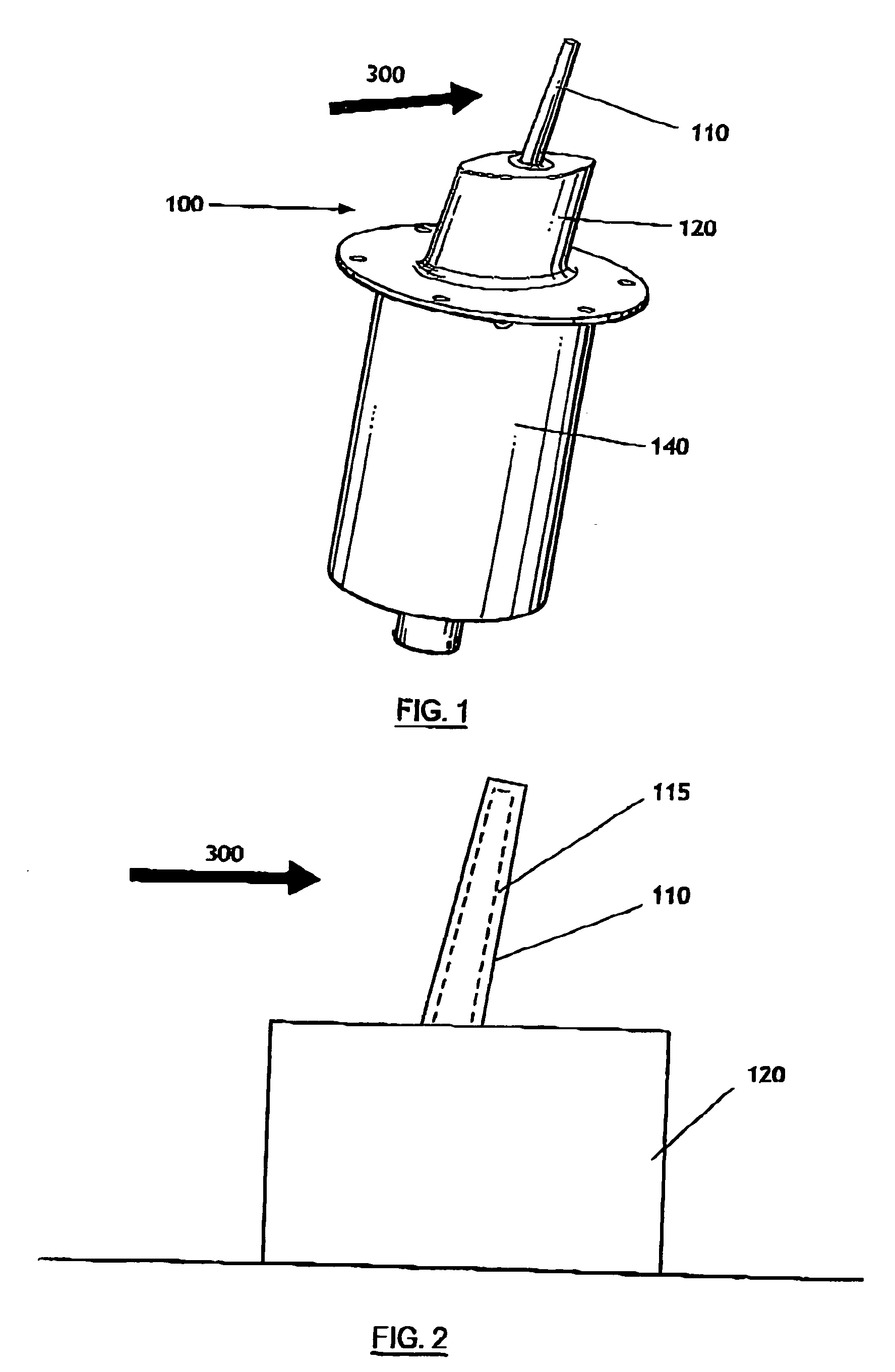
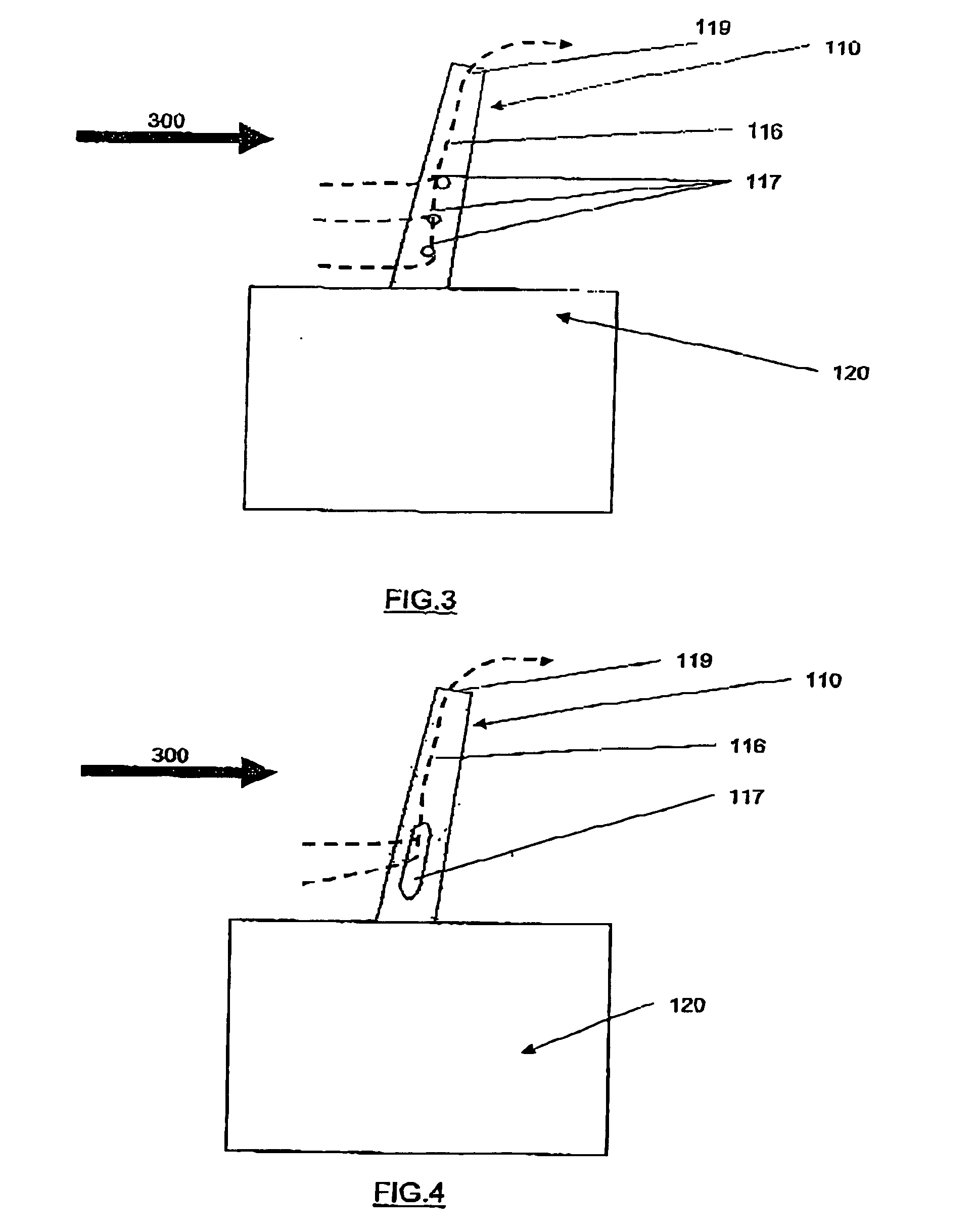
[0059] As shown in FIG. 1, an ice detection assembly 100 according to the invention comprises: [0060] a mast 120; [0061] an elongated finger 110 extending into the surrounding air from the mast 120 to which it is bonded, usually transverse to the air flow; [0062] a system for cooling at least a part of the detection assembly (not shown in FIG. 1).

[0063] The mast 120 may be in the shape of a symmetric wing profile or of an ellipse.

[0064] An attachment flange 140 is usually provided to hold the detection assembly 100 in place and fixed onto an attachment surface outside the aircraft.

[0065] A box (not shown) is fixed to the flange 140, extending inwards into the aircraft through the attachment surface, for containing and for protecting electrical connections and circuits necessary for operation of the detection assembly 100. In particular, this box comprises the different electrical equipment, electronic cards and components used to supply and control the frequency excitation of the...


PUM


Abstract

Ice detection assembly (100) designed for installation on an aircraft, comprising a vibrating finger (110) and a mast (120), the vibrating finger (110) extending into the air from the mast (120) and capable of being vibrated by vibration means at a resonant frequency that is sensitive to an ice deposit on its surface, characterised in that it comprises a cooling system capable of cooling at least part of the detection assembly (100).

Description

FIELD OF THE INVENTION [0001] This invention relates to an ice detection assembly to be installed on an aircraft, such as a plane, to detect ice accretion on surfaces of the aircraft. BACKGROUND OF THE INVENTION [0002] Ice detection is usually used in aviation during flight to indicate the presence of ice in air surrounding the aircraft. [0003] The reliability and precision of this detection are very important since ice can deteriorate the properties of some parts of an aircraft, such as the aerodynamic properties of wing or engine intake parts, and increase the mass of the aircraft. This can then lead to loss of lift and controllability of the aircraft. [0004] The detection assembly comprises an intrusive part immersed in the air flow surrounding the aircraft, and is typically placed at locations on the aircraft subject to particularly severe icing conditions, such as the aircraft nose or wings, to detect the first signs of ice appearance. [0005] As shown in FIG. 1, a known detecti...

Claims


Application Information

Patent Timeline
IPC IPC(8): B64D15/20G01K1/14
CPCB64D15/20
Inventor BARRE, CYRILLAPEYRONNIE, DAVIDSALAUN, GURVAN
Owner AUXITROL
Learn More